Robotic Quadruped Leg [2025]
Summary and Key Details
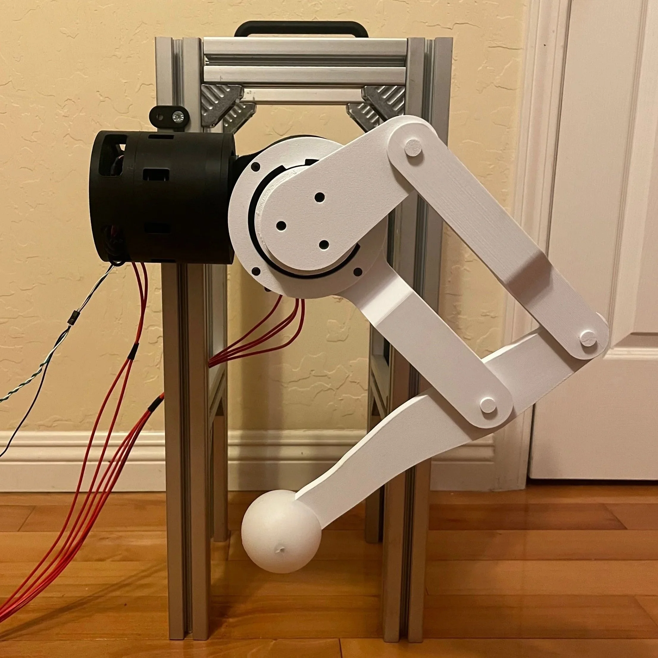
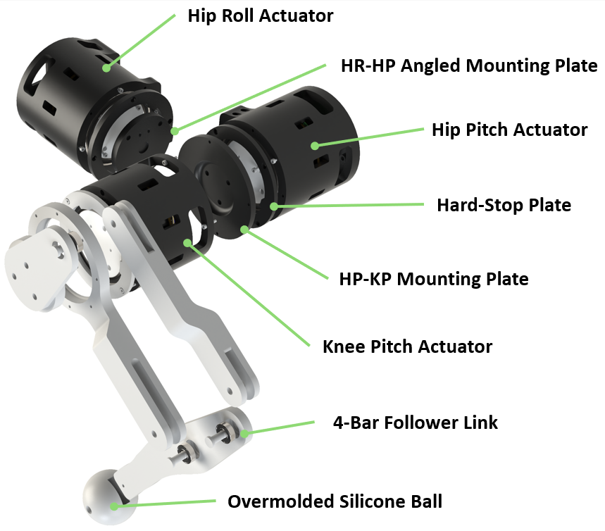
Developed a 3 DoF leg including custom 8:1 planetary gearboxes and a 4-bar linkage to replicate quadruped gait
Implemented inverse kinematics and trajectory planning over CAN bus, enabling closed-loop BLDC control
Designed actuator subassemblies to simplify manufacturing and utilized hard stops for current-based homing
Used improved actuators from of my Planetary Project
Specifications
3x Custom Actuators
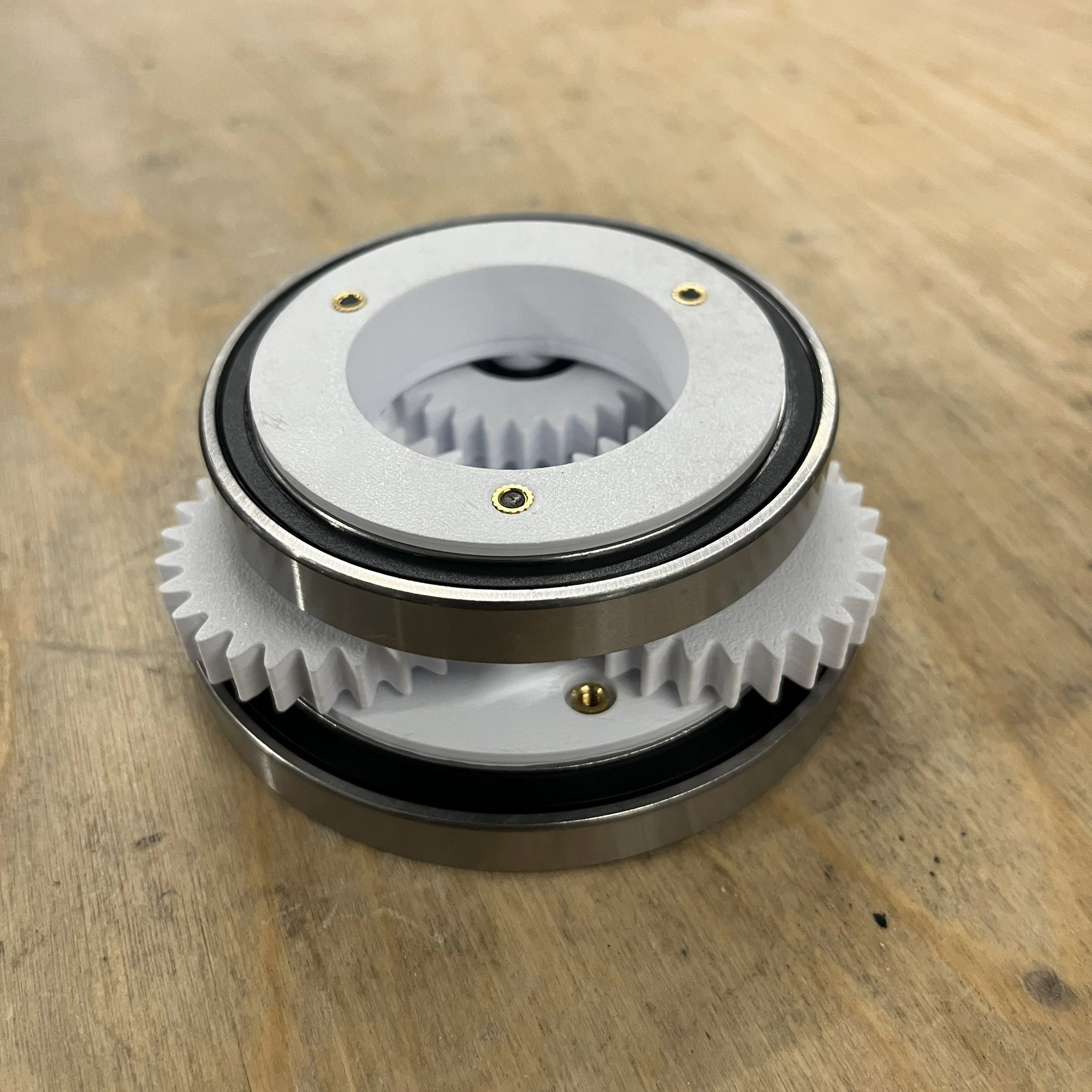
8:1 Planetary Gearboxes
90 KV BLDC Motor, ODrive S1 Controller
Magnetic Encoder for Closed-Loop Control
4-Bar Linkage for Knee Flexion/Extension
Teensy 4.1 for High-Level Logic
30A Over Molded Silicone Feet for Traction
6S 5200mah LiPo Battery
Continuous Current Output Force (Neutral): 101 N
Total Mass: 3.9 kg
Leg Kinematics and Motion Planning
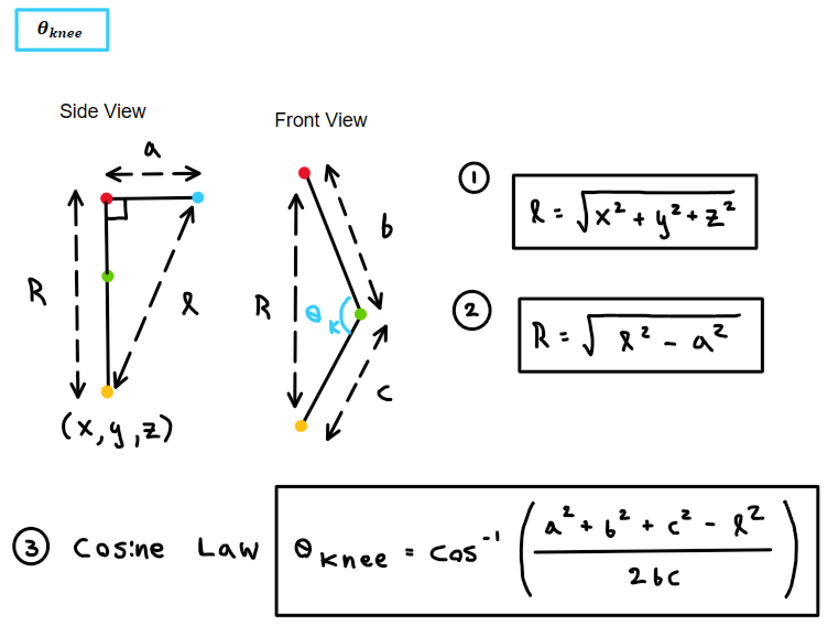
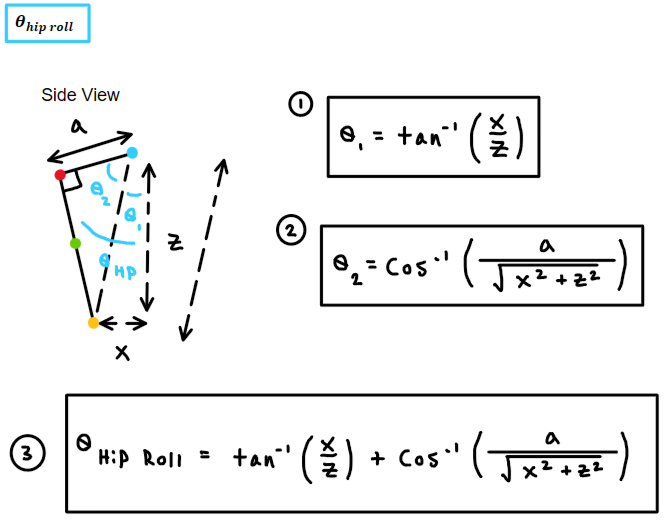
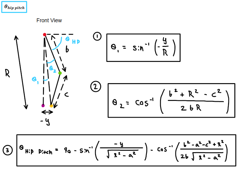
The leg’s inverse kinematics were derived to calculate joint angles for a desired XYZ position, with forward kinematics used to determine the foot position from current joint angles.
I implemented a trajectory planner that interpolates linear, sinusoidal, and circular paths, discretizes them into waypoints, and applies the IK equations at each step, producing predictable motion.
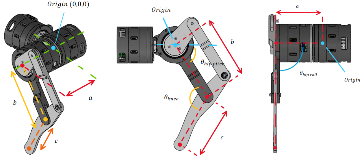
Inverse Kinematic Derivations
Movements
Forward Stepping (Sinusoidal)
Side Stepping (Sinusoidal)
Circular Motions
Sideways Circular Motion
Linear Motions
Fast Steps
Box Steps
Homing Procedure (Hard Stops)
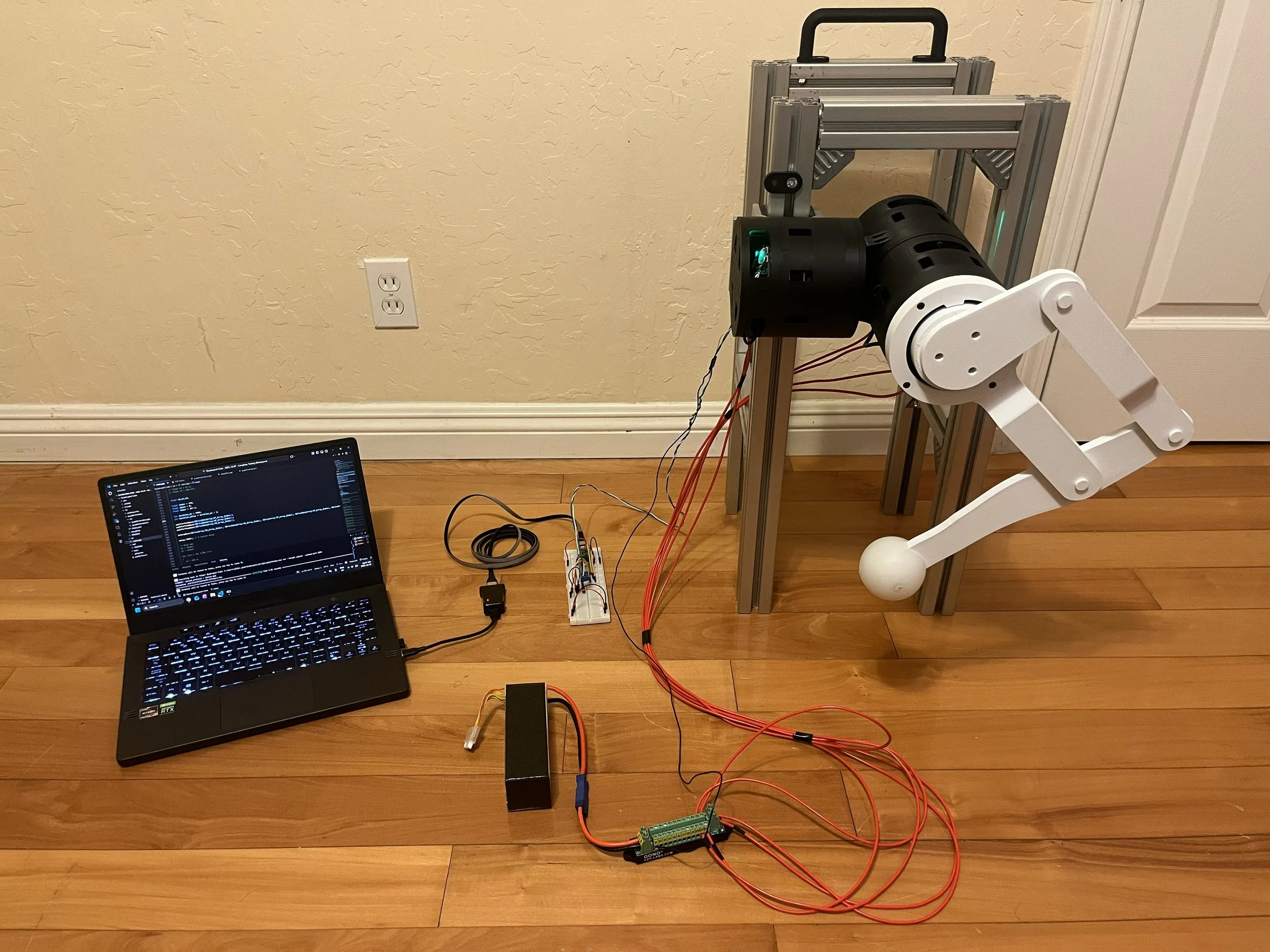
Electrical Architecture
Each actuator has an ODrive S1 mounted behind the motor, leveraging the onboard magnetic encoder for closed-loop position and velocity control.
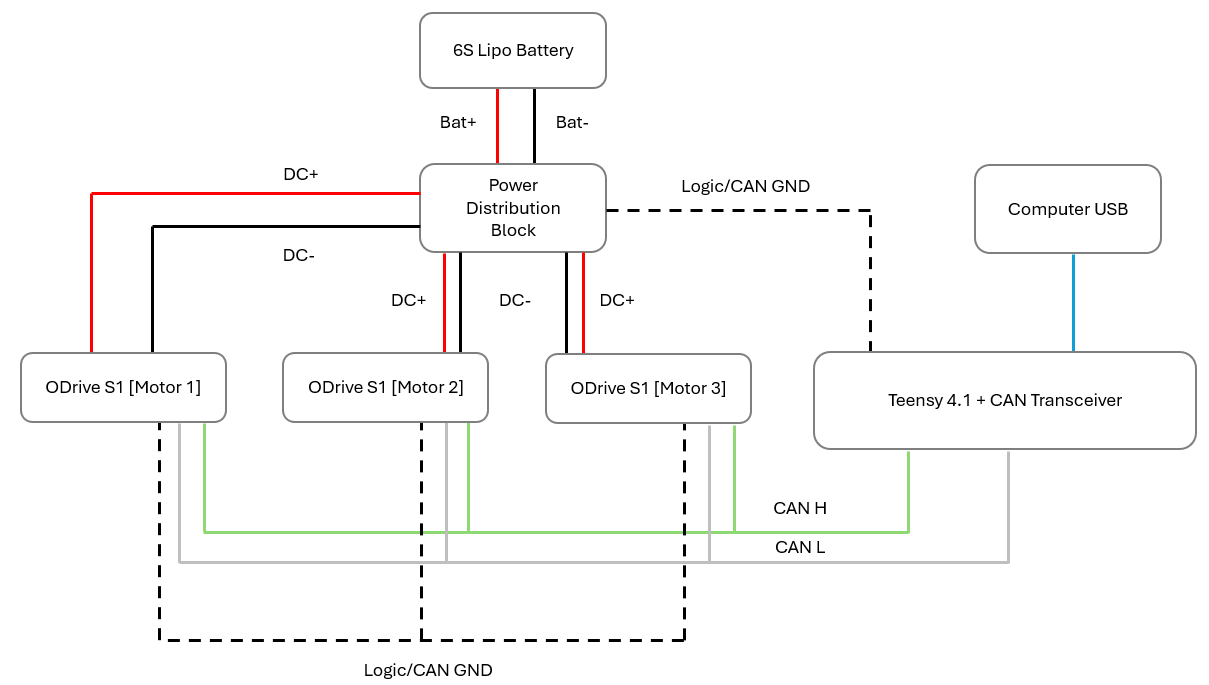
A Teensy 4.1 serves as the central controller, transmitting and receiving CAN messages via an external CAN transceiver. The ODrives are connected over a daisy-chained CAN bus, reducing wiring complexity.
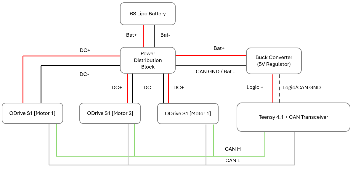
Power is supplied by a 6S LiPo battery through a power distribution block, with CAN ground tied to DC- to establish a common reference and prevent ground loops.
USB Wiring Diagram
External Power Wiring Diagram
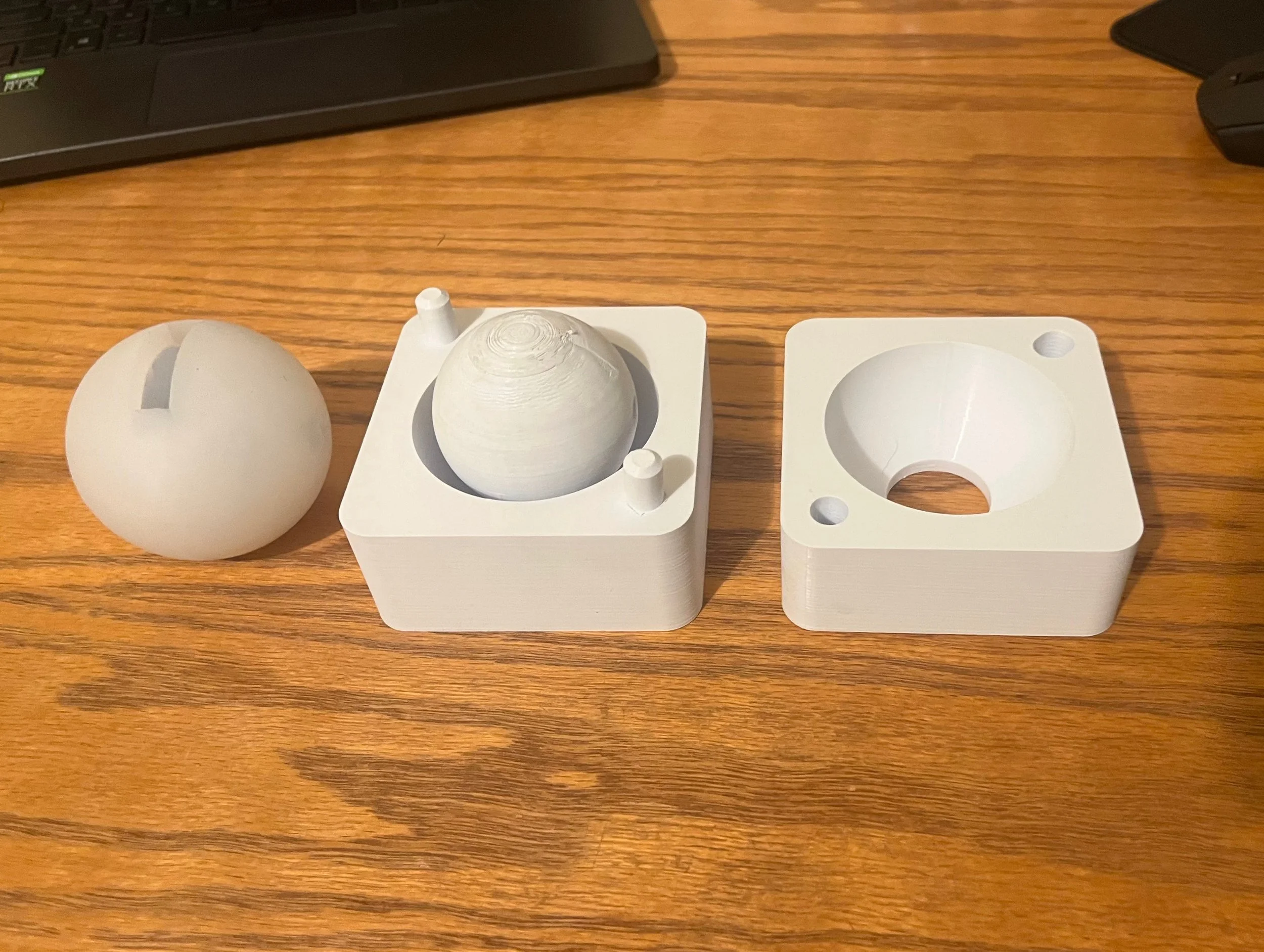
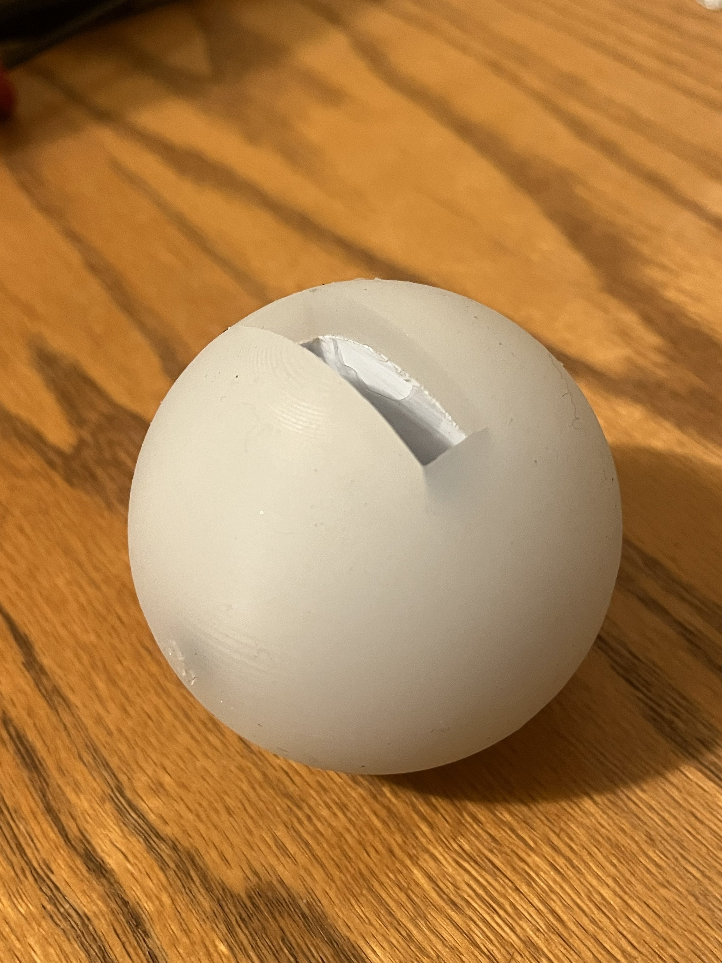
End-Effector Silicone Overmold
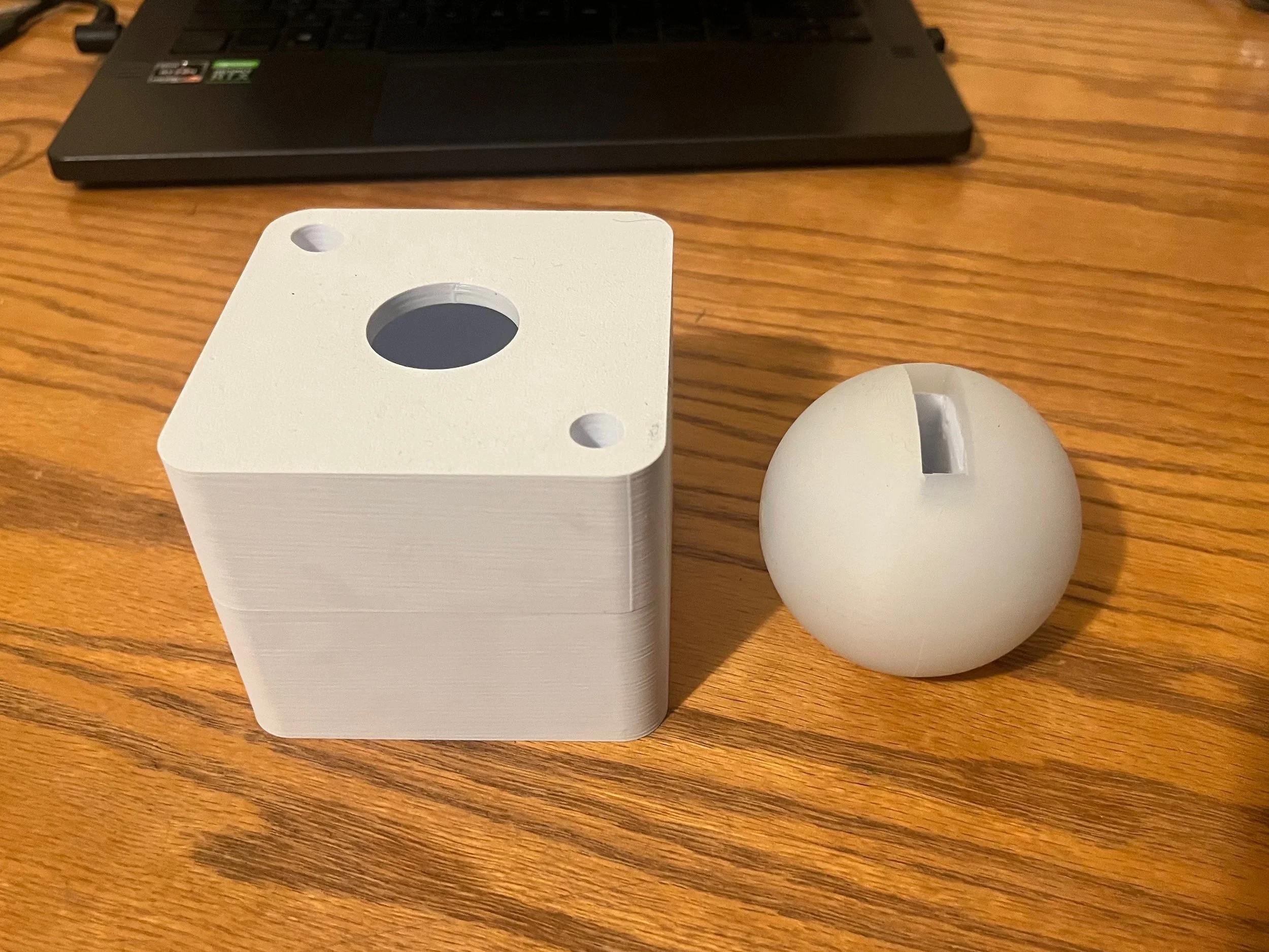
To increase friction at the ball end of the leg, I designed and 3D-printed a two-part mold and overmolded a 5 mm thick, 30A Shore hardness silicone layer. This layer increases the coefficient of friction, improving traction while also introducing passive compliance at the ground interface.
For future iterations, the underlying ball geometry should include mechanical retention features such as grooves or undercuts, since the silicone does not strongly adhere to the printed substrate. In the current design, the silicone is mechanically retained once the leg linkage is inserted, locking the overmold in place during operation.
Additional Photos and Videos
Continuous Current Lifting Force
Prototyping Aftermath
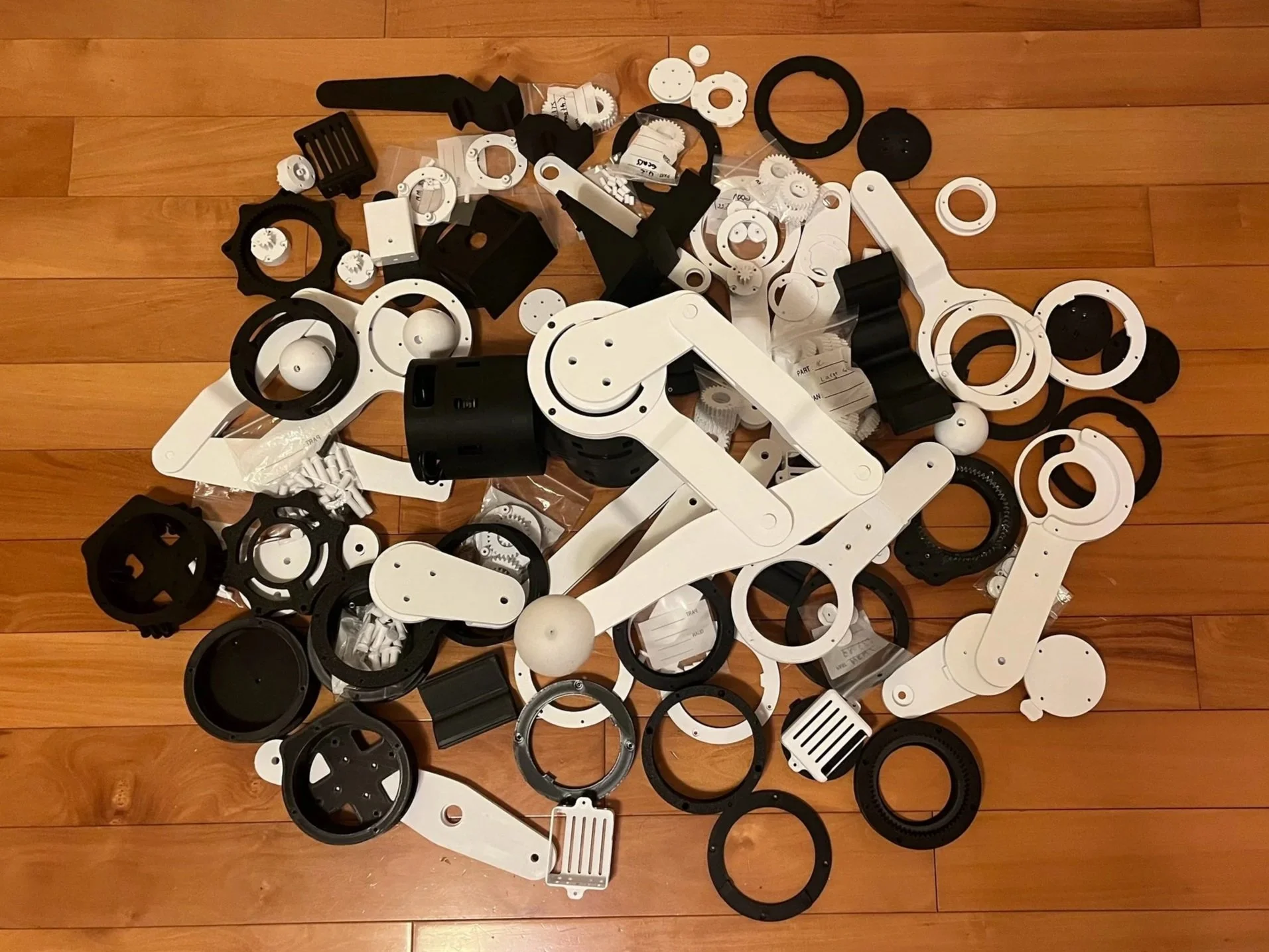
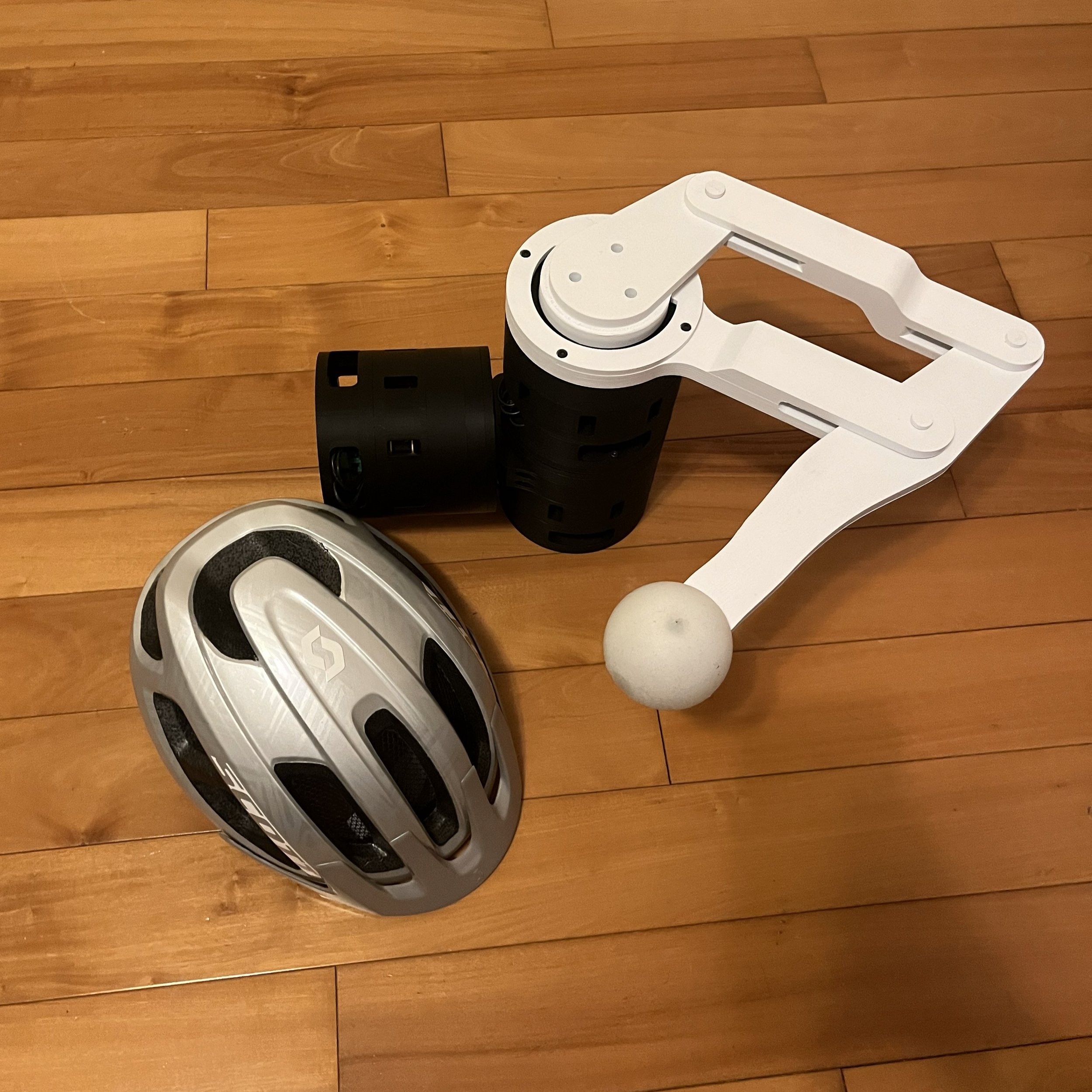
Photo for Scale
Planetary Carrier
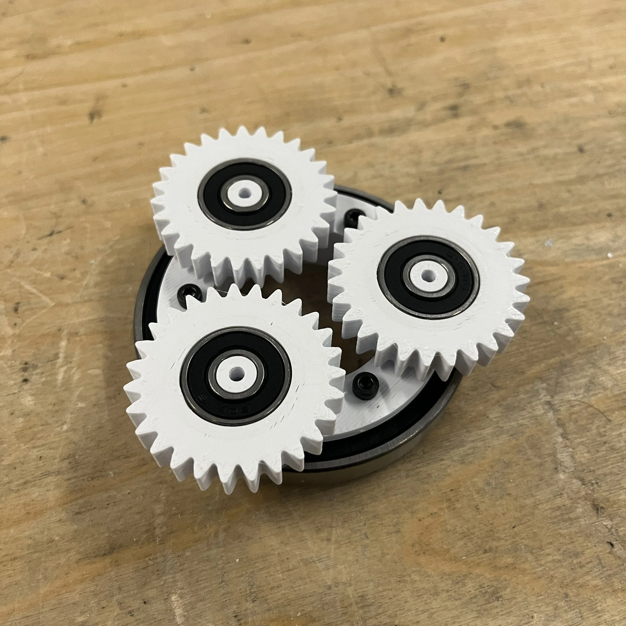
Gearbox Output Assembly