6-DOF Robot Arm [2026]
Summary and Key Details
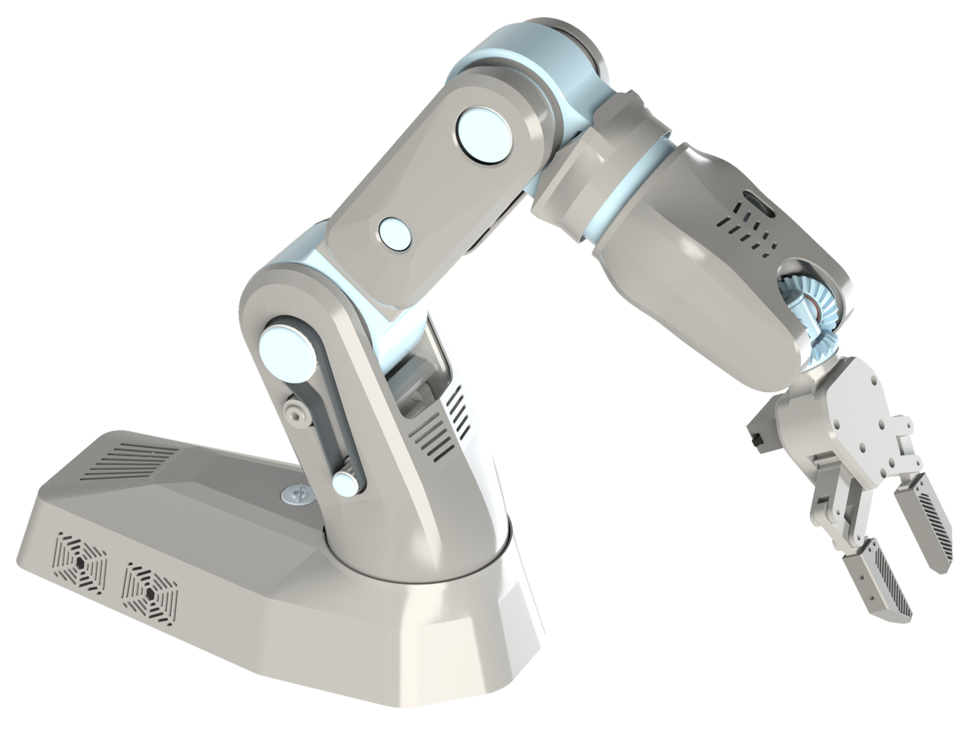
A robotic arm with cycloidal and planetary gearboxes, capable of dexterous manipulation and lifting 3 kg while costing under $300
Compliant gripper with a differential wrist mechanism enables reliable grasping of irregular objects in constrained spaces
Implemented mechanical hard stops, active cooling for electronics, and magnetic A-surface panels for aesthetics


Mechanical Subsystems
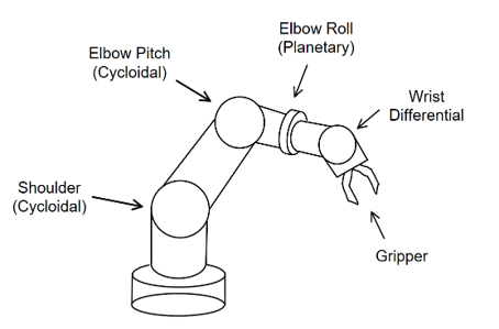
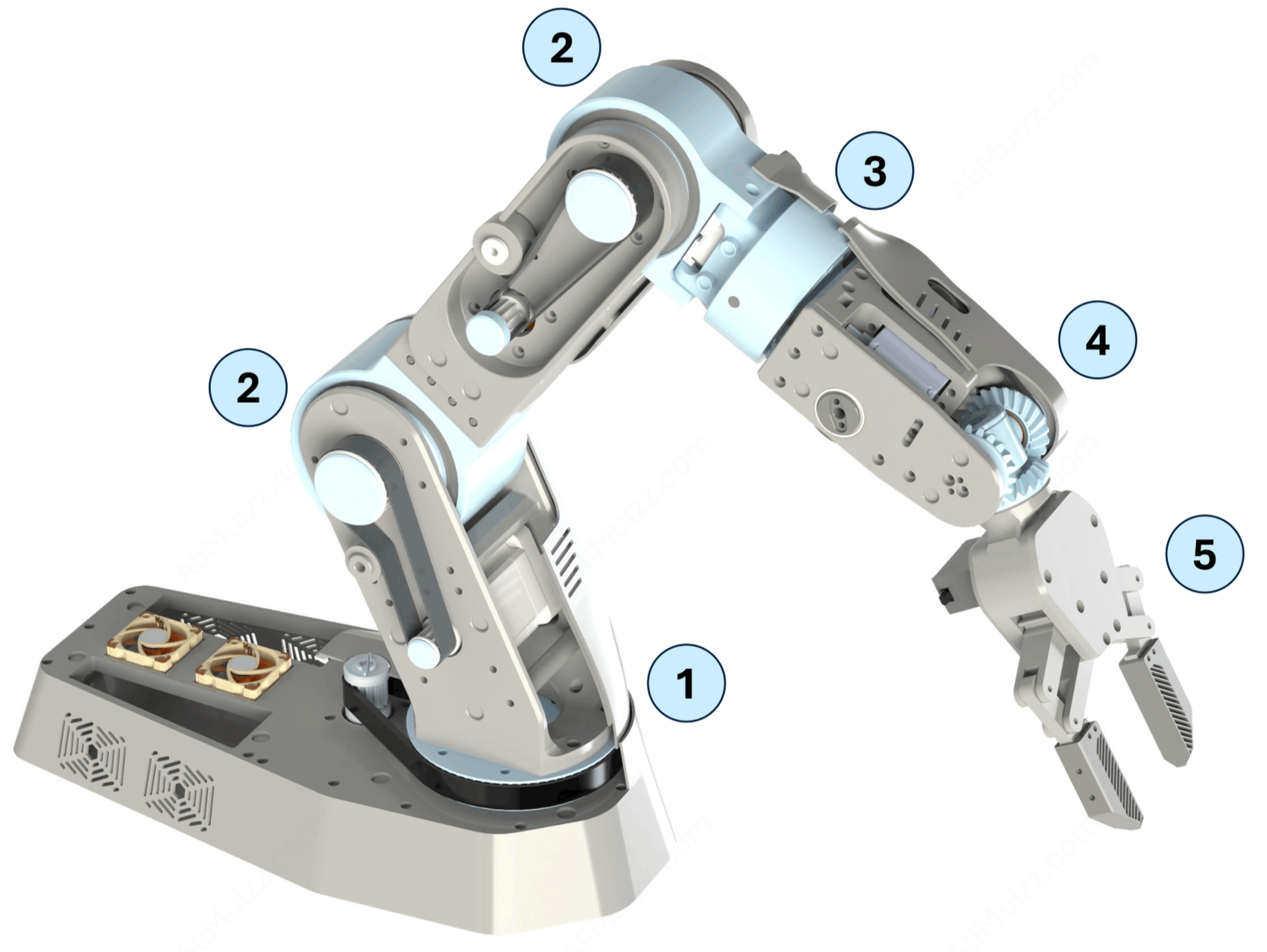
The mechanical design consists of 6 main subsystems.
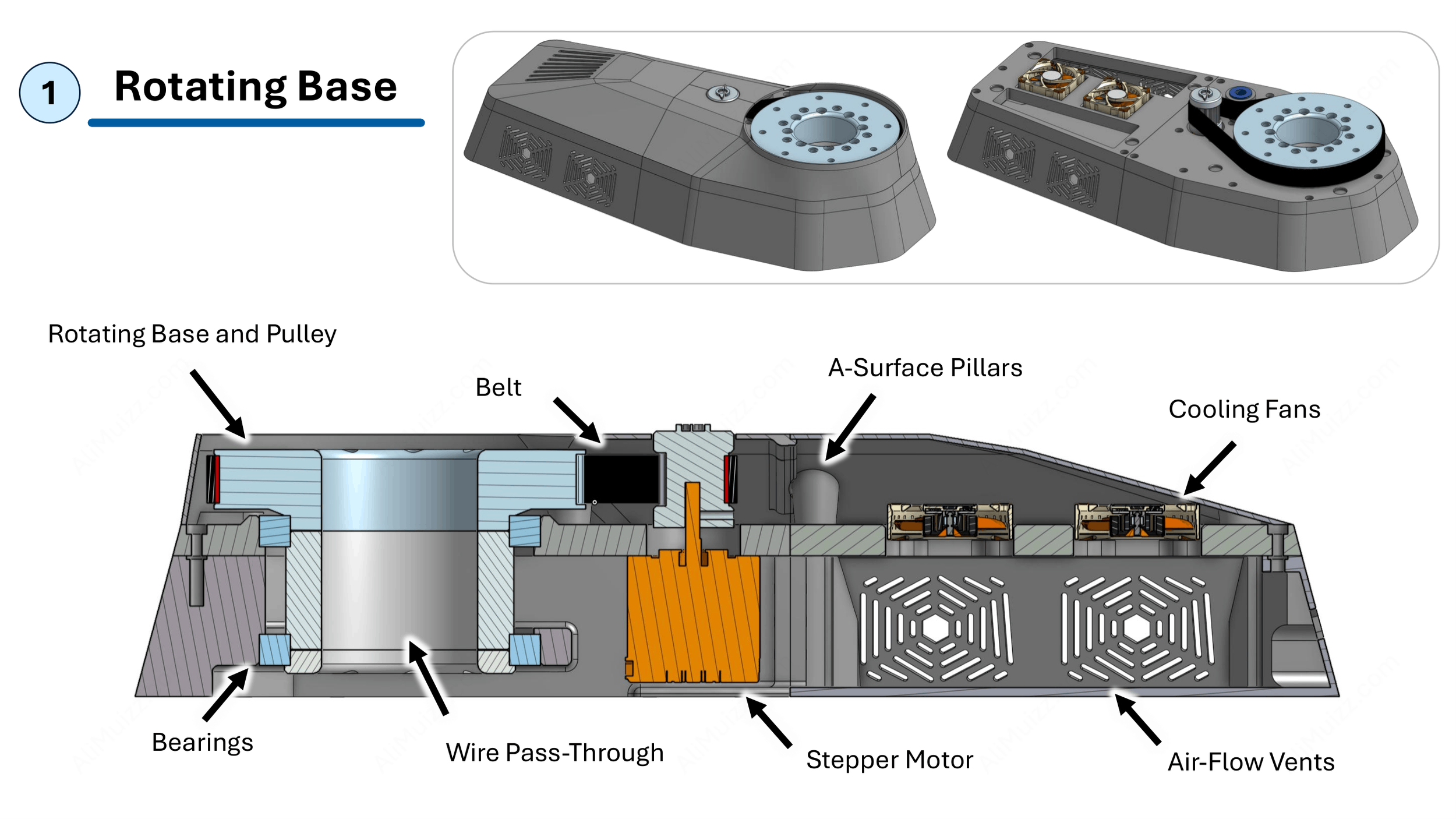
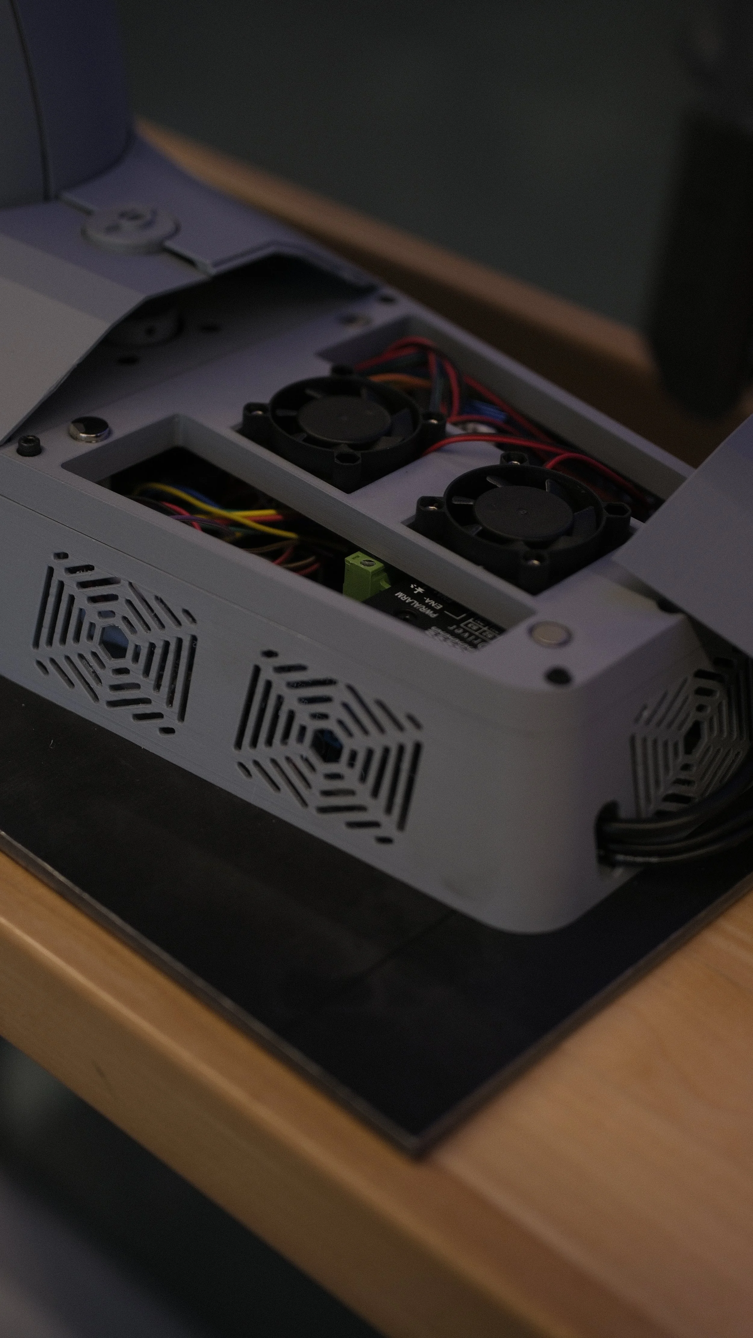
[1] Rotating Base: Belt-Driven Motion, also acts as the electronic enclosure with active cooling using two fans
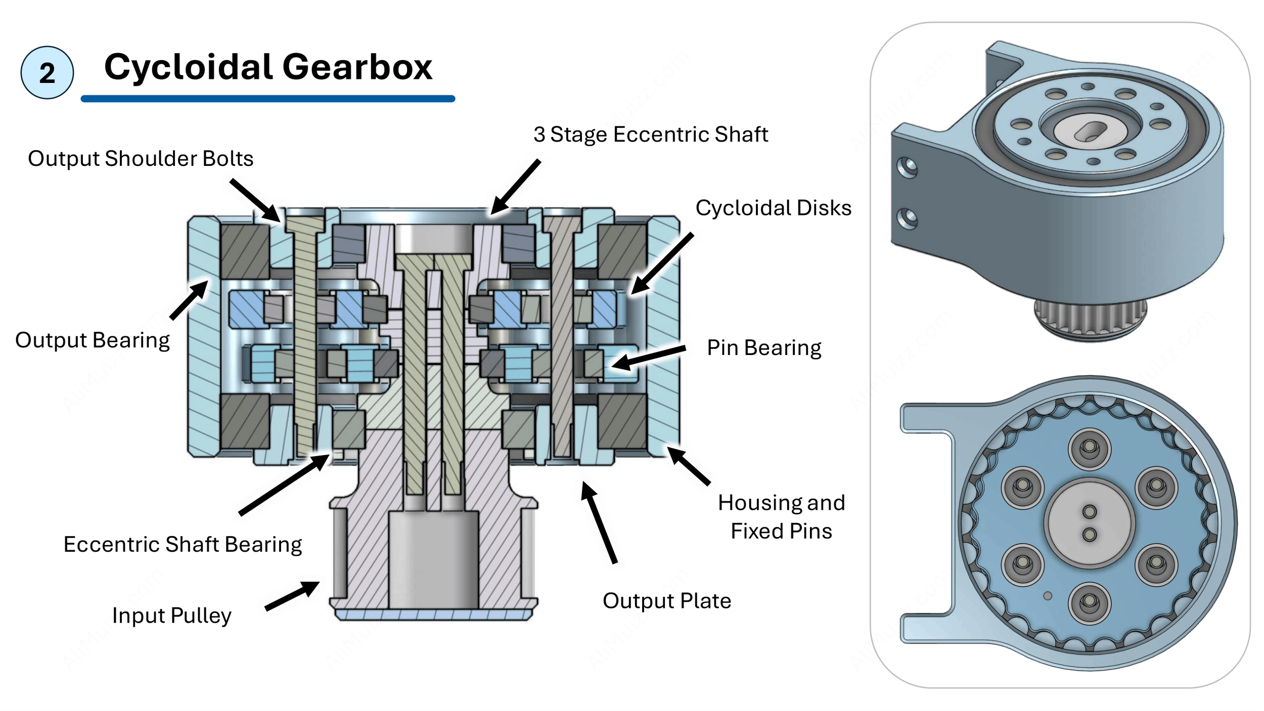
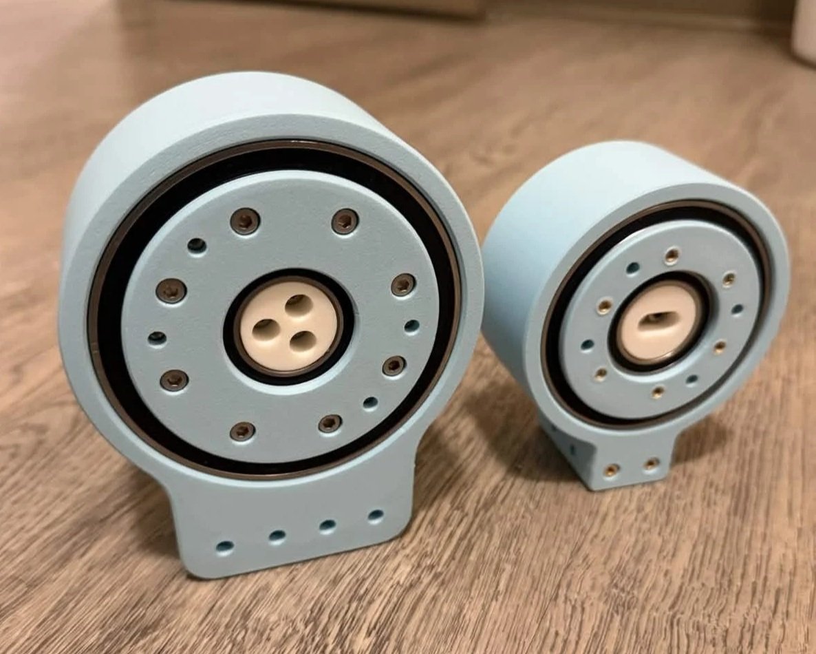
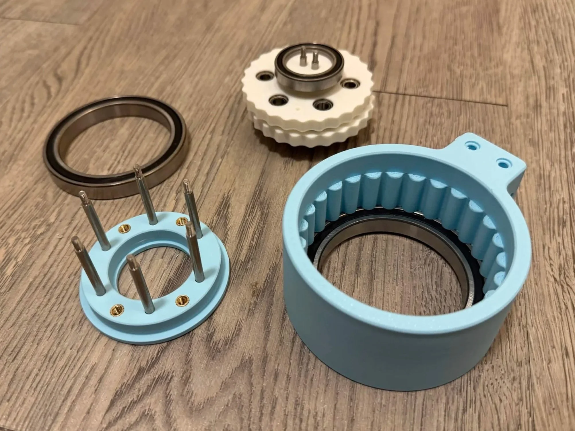
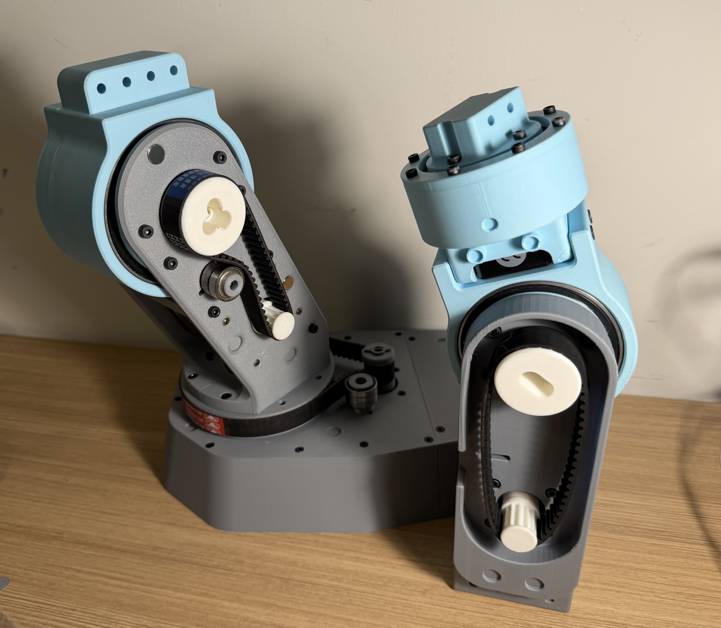
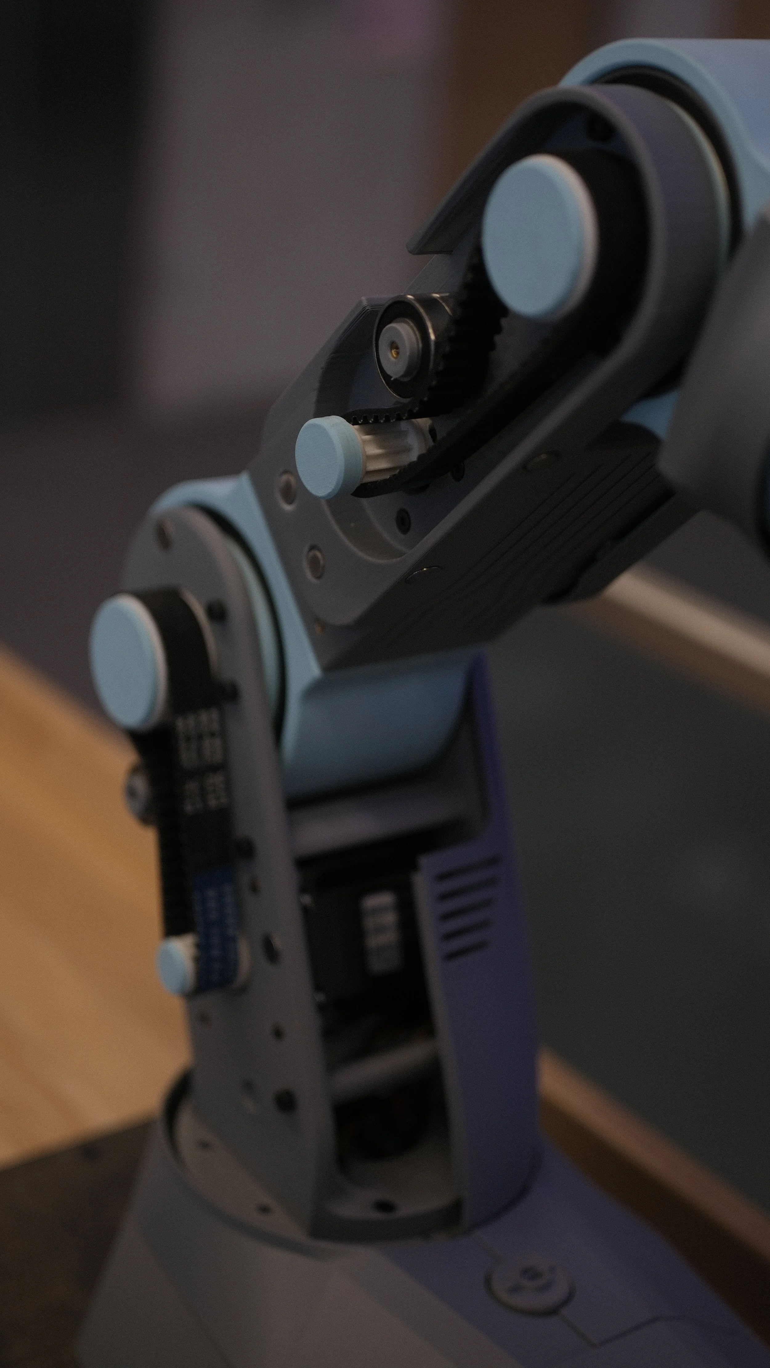
[2] Cycloidal Gearbox: Utilized in the shoulder and elbow pitch joints, driven by a belt and utilizing the housing as the output
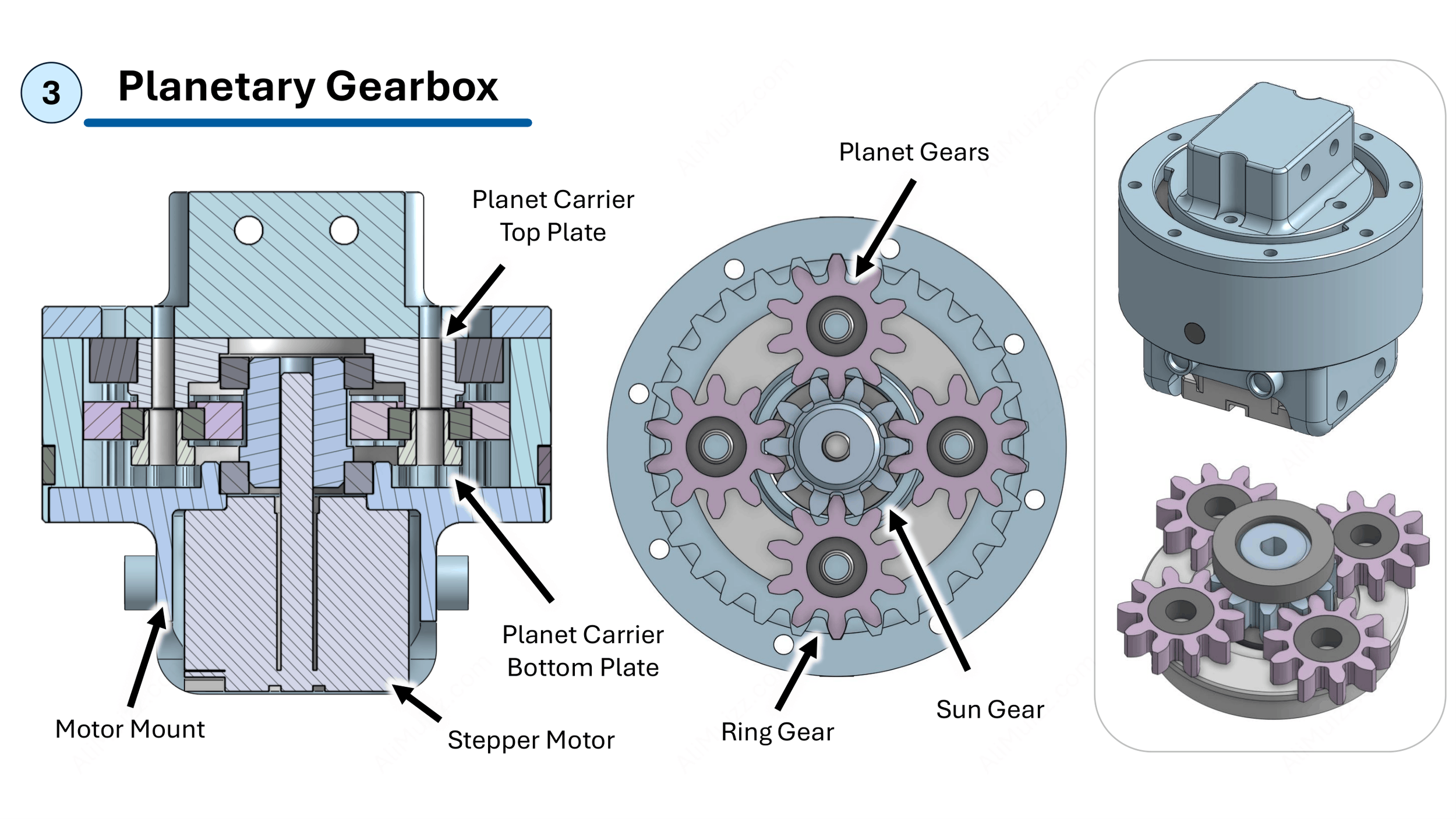
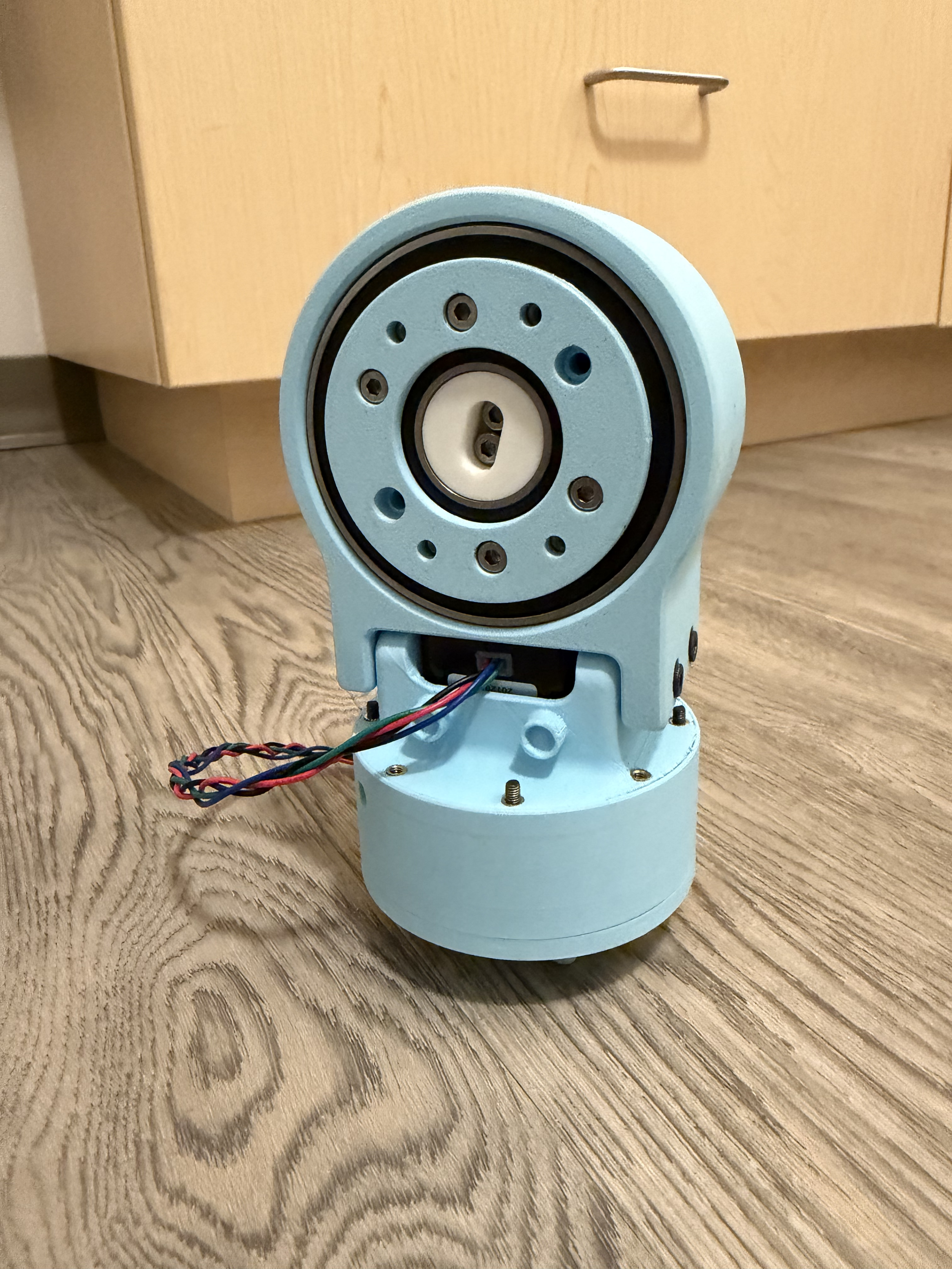
[3] Planetary Gearbox: Provides the 6th DOF (elbow roll) which allows the gripper to pitch sideways instead of vertically
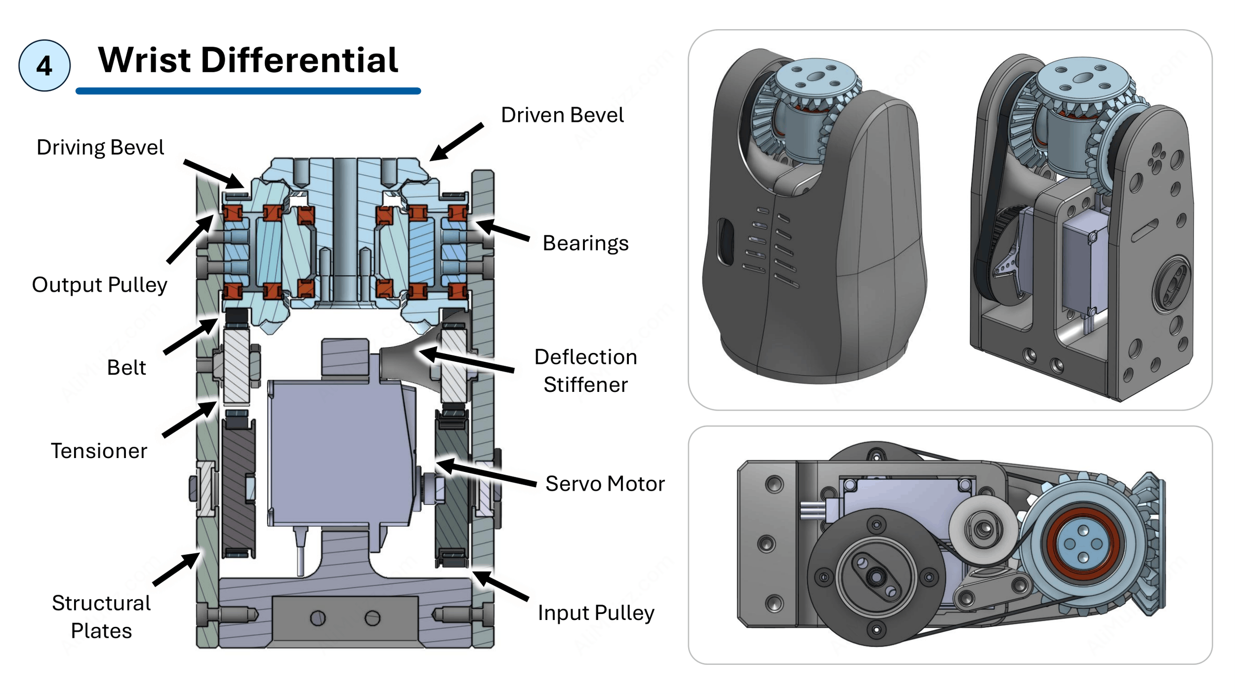
[4] Wrist Differential: Bevel gear differential enabling both wrist articulation and gripper roll
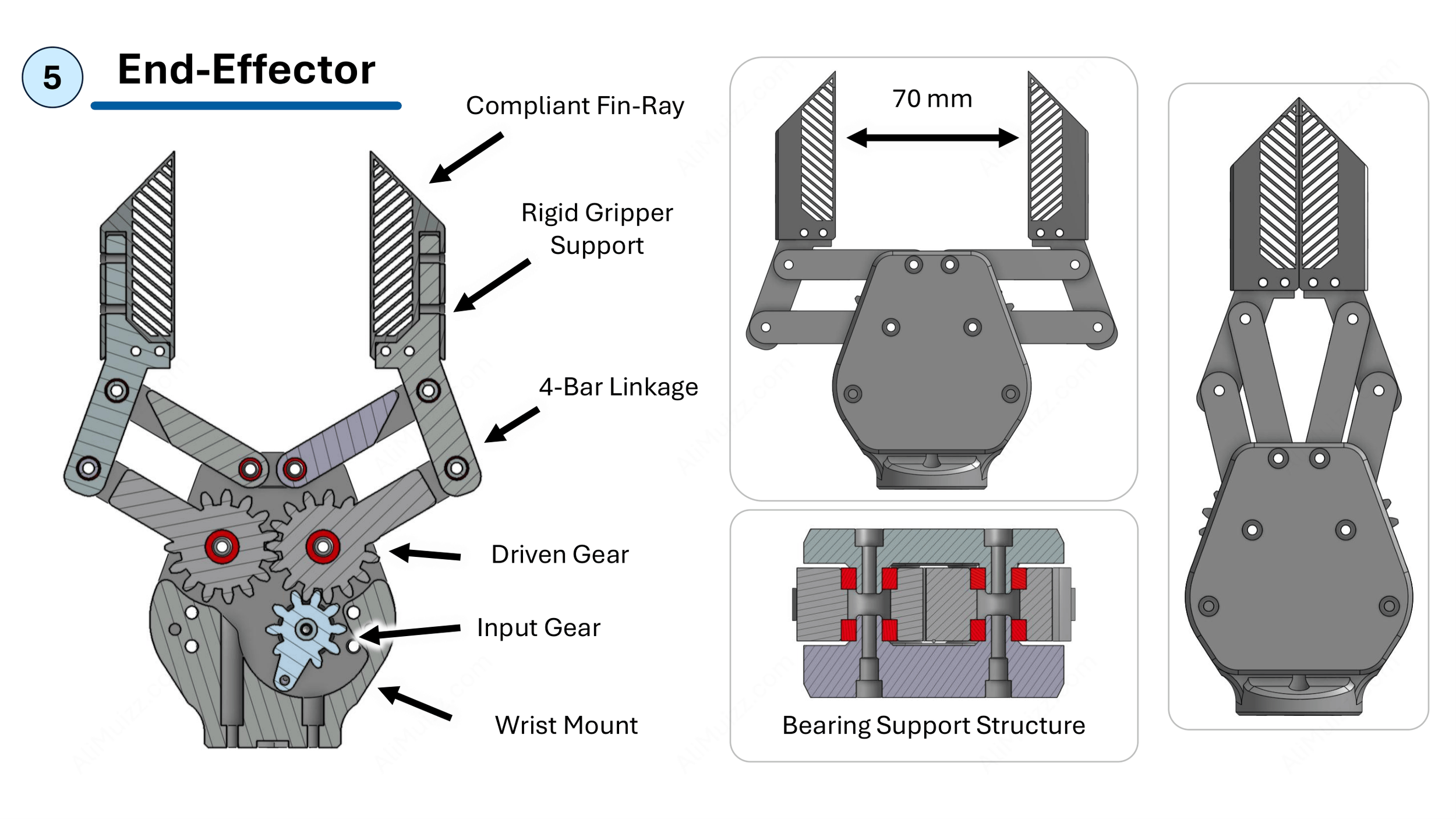
[5] End-Effector: A parallel 4-bar linkage with fin-ray grippers providing compliance to grasp difficult objects
Compliant Gripping
Demonstration of the gripper securely grasping objects across a range of shapes and geometries
Billiard Ball
Mouse
Egg
Pencil
Load Capacity Test
The shoulder and elbow joints demonstrate stable articulation at maximum reach with a load of a 1.5 kg (in the form of my water bottle). Additional testing shows that the actuators can support up to 3 kg, although, the wrist begins to flex and pitch at this extreme.
Overall, the assembly shows a high strength-to-weight ratio, lifting 60% of its total mass in it’s worst-case scenario.
1.5 Kg Shoulder Lift
1.5 Kg Elbow Lift
3 Kg Shoulder Lift
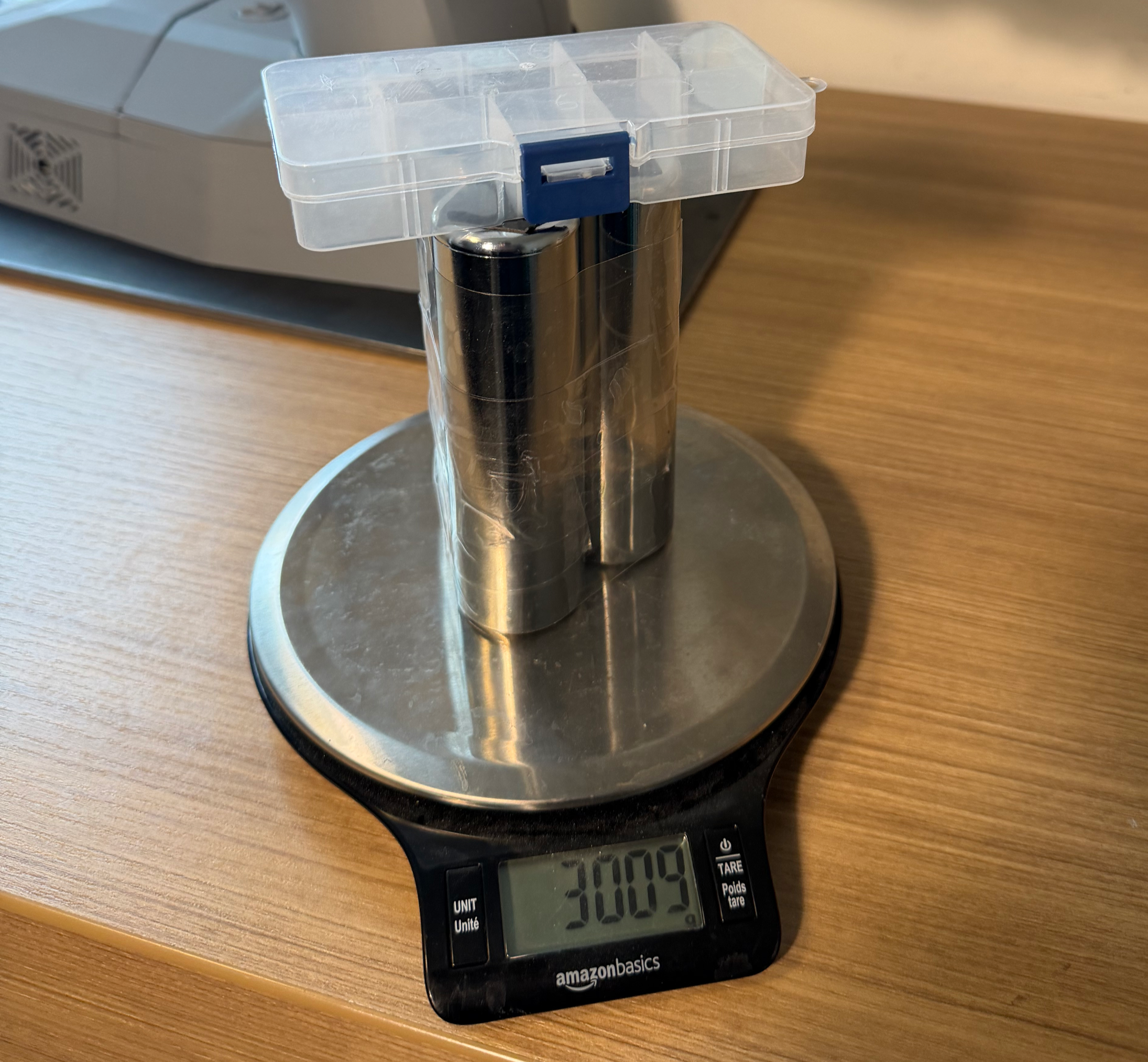
Mass Validation
Additional Photos and Videos
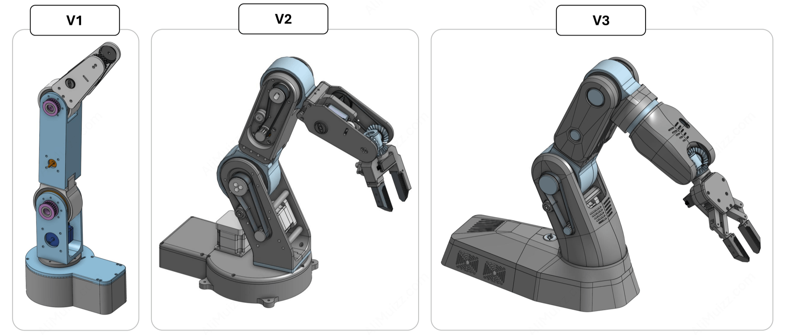
Design Iterations
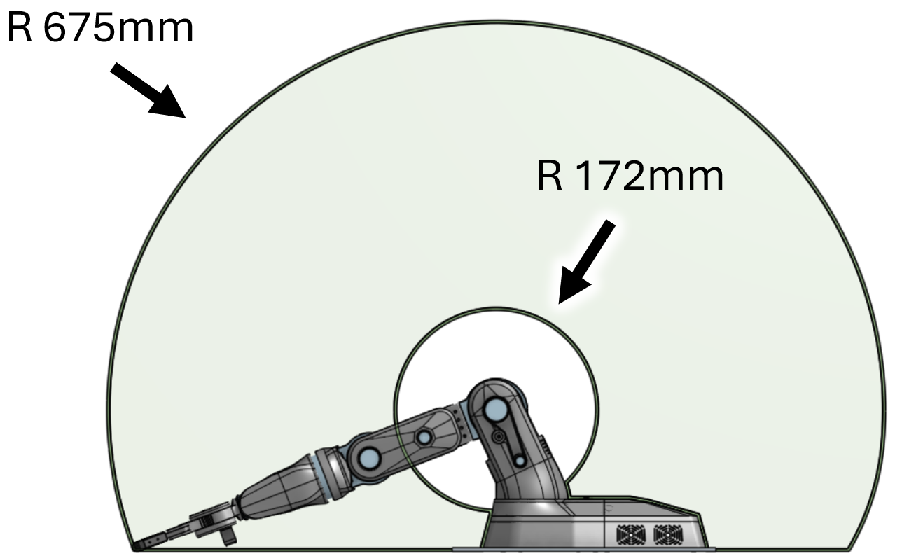
Range of Motion Plot
Cycloidal Gearboxes
Cycloidal Components
Shoulder and Elbow Assemblies
Elbow Pitch + Elbow Roll
A-Surface Panels Removed

Differential Mechanism and Belt Drives

Electronic Enclosure
Design Specifications
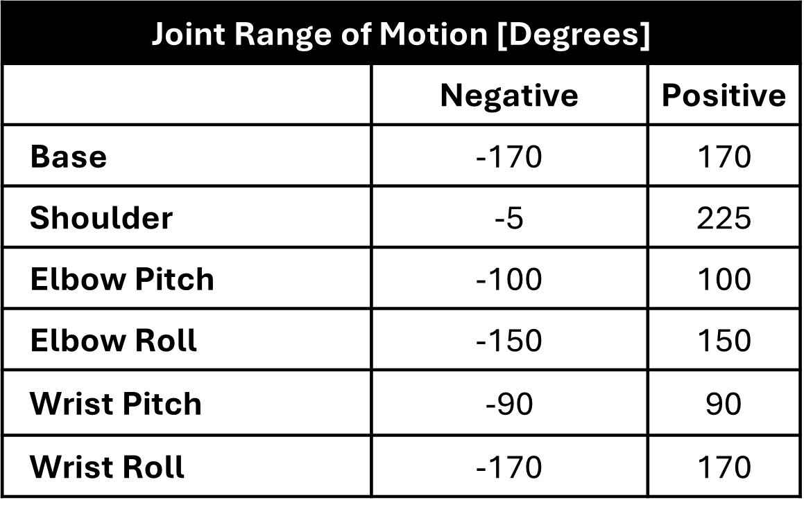
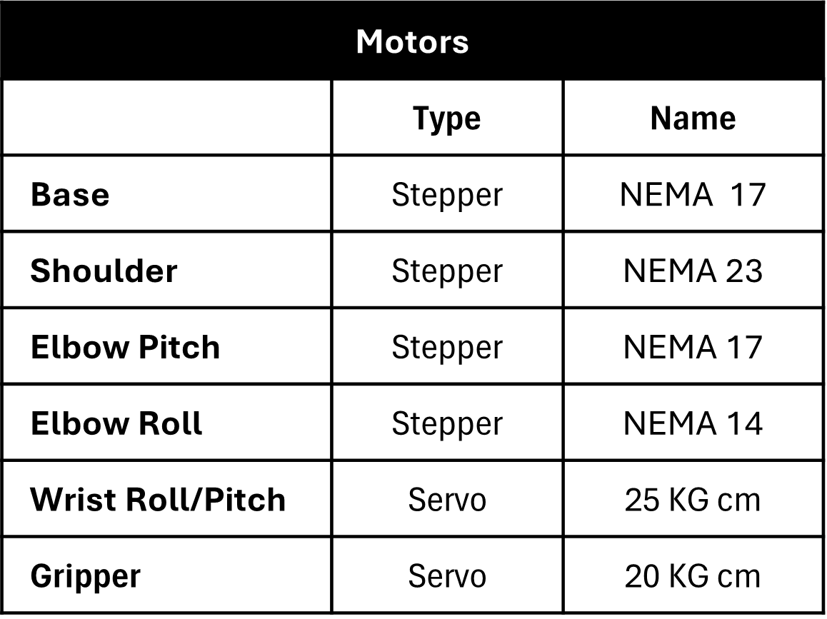
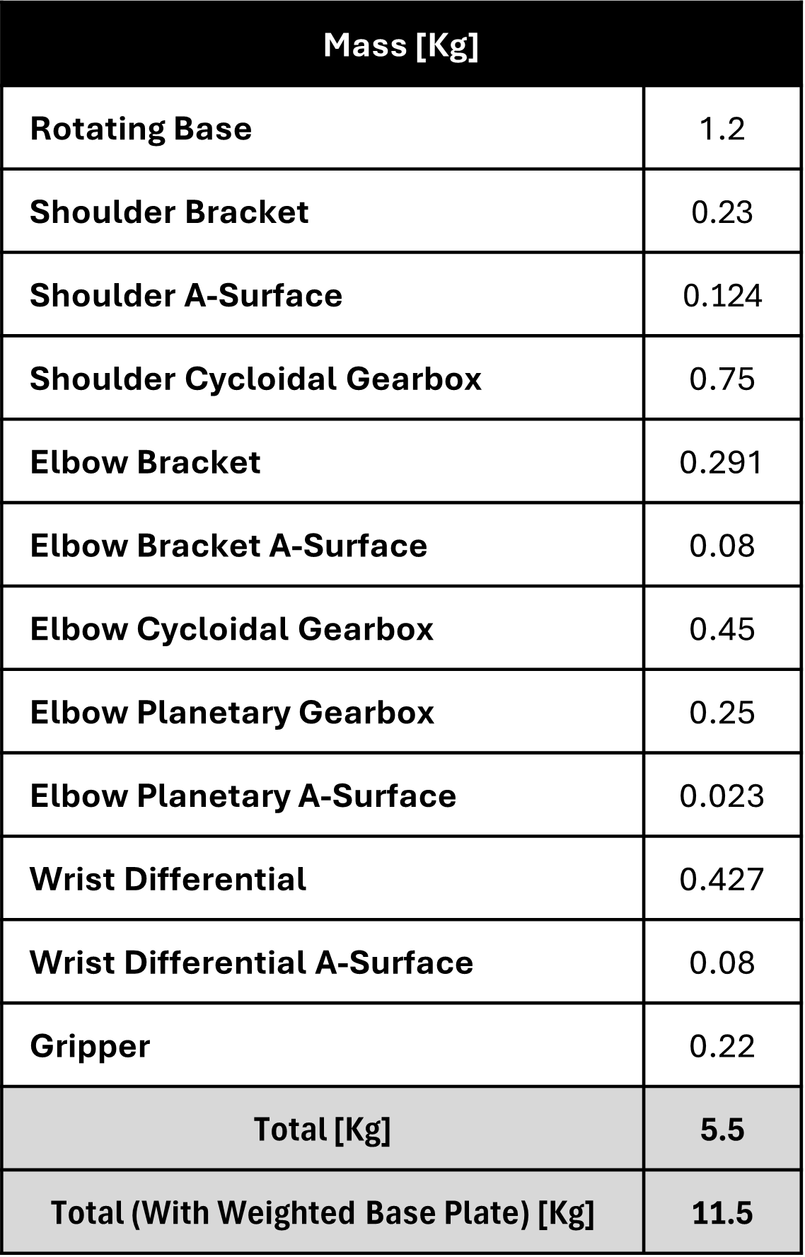
The main specifications defining the design of the robot are depicted in the tables below. This includes:
The range of motions determined by mechanical hard stops for each joint
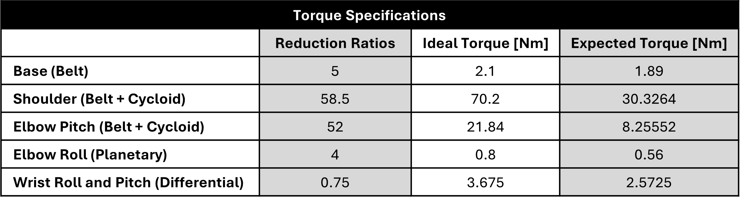
The joint torques, determined through engineering calculations and validated through testing
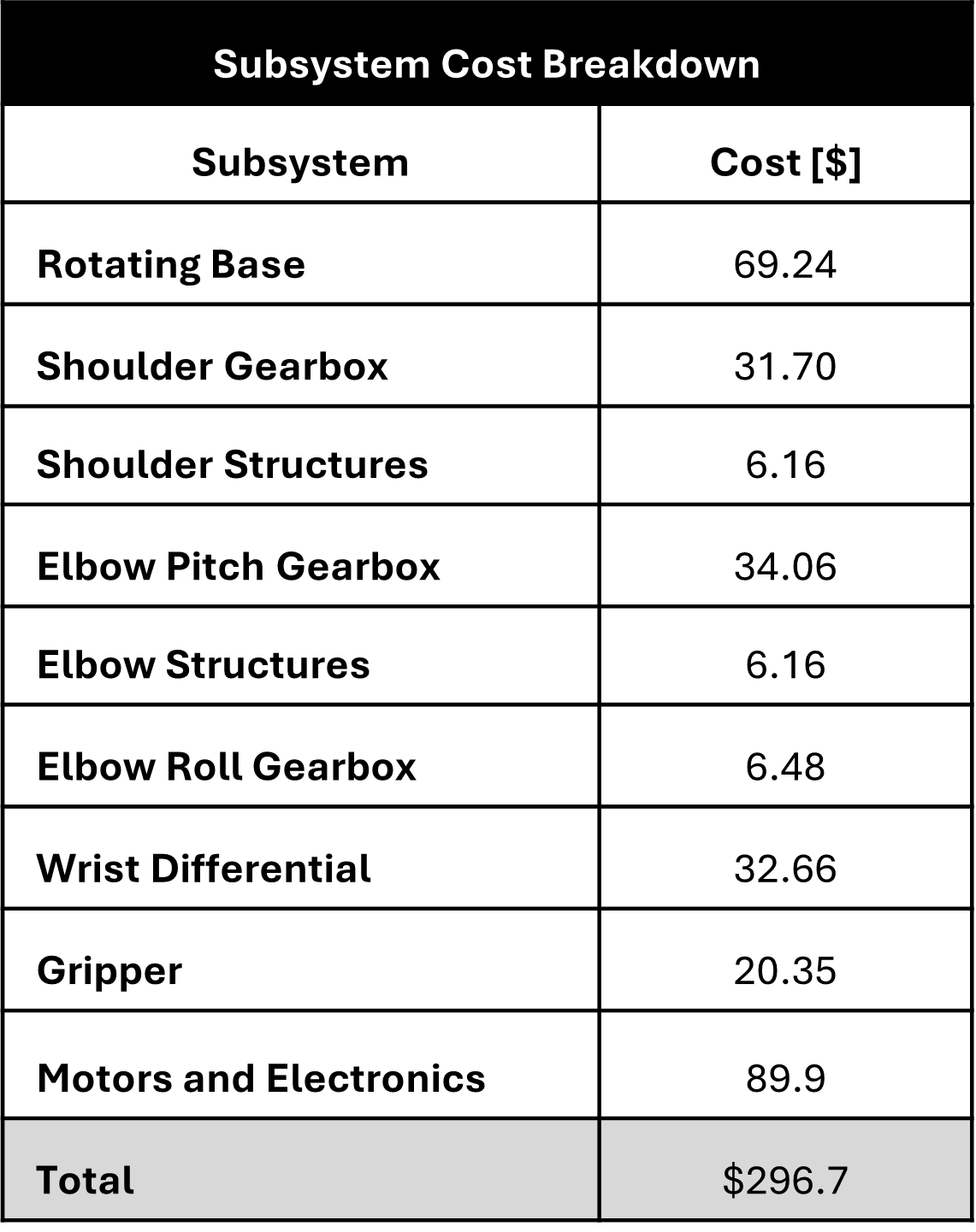
The mass and cost breakdown of each subassembly