Mechanical Push-Button Case [2024]
Summary and Key Details
Designed a mechanical push-button with a 3N actuation force and 6 mm button travel
Validated components with SOLIDWORKS FEA to ensure they withstood operational loads

Project Premise
I’ve always been fascinated by the mechanics behind everyday objects. Intrigued how something so simple like a latch can be designed in countless ways, I was inspired to create one myself. I settled on making a push-button case for my glasses, since it’s something I would always use.
Design Specifications: Button Release Latch
Button Actuation Force of 0.3 kg (~3 N)
After running some tests, I found that 0.3 kg allowed for a comfortable button press, without worry of accidental triggering.
Button Travel Distance of 5 mm
I wanted an emphasis on the mechanical nature of the button. This led to choosing half a centimeter of travel
Latching Force of 10 N
In order to re-latch the box, with some research I found that a range of 9-20 N would be appropriate.
Initial Concepts
Force and Displacement Calculations
Prior to designing the push-button system, I derived symbolic calculations. These are later used in order to determine parameters needed for the desired actuation distance.
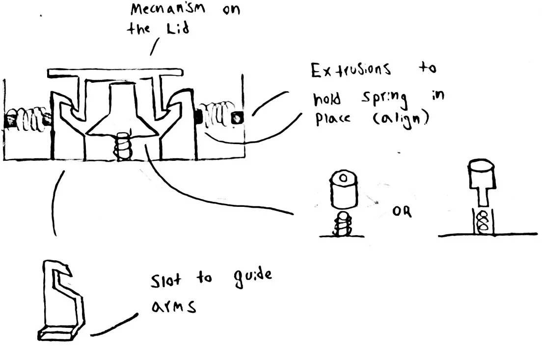
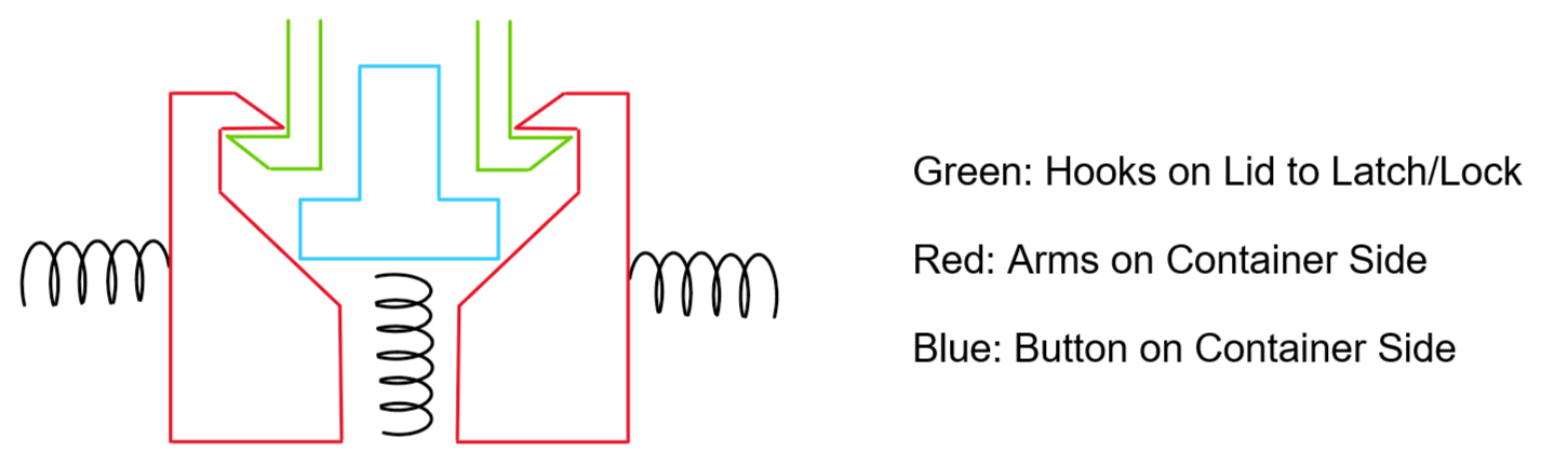
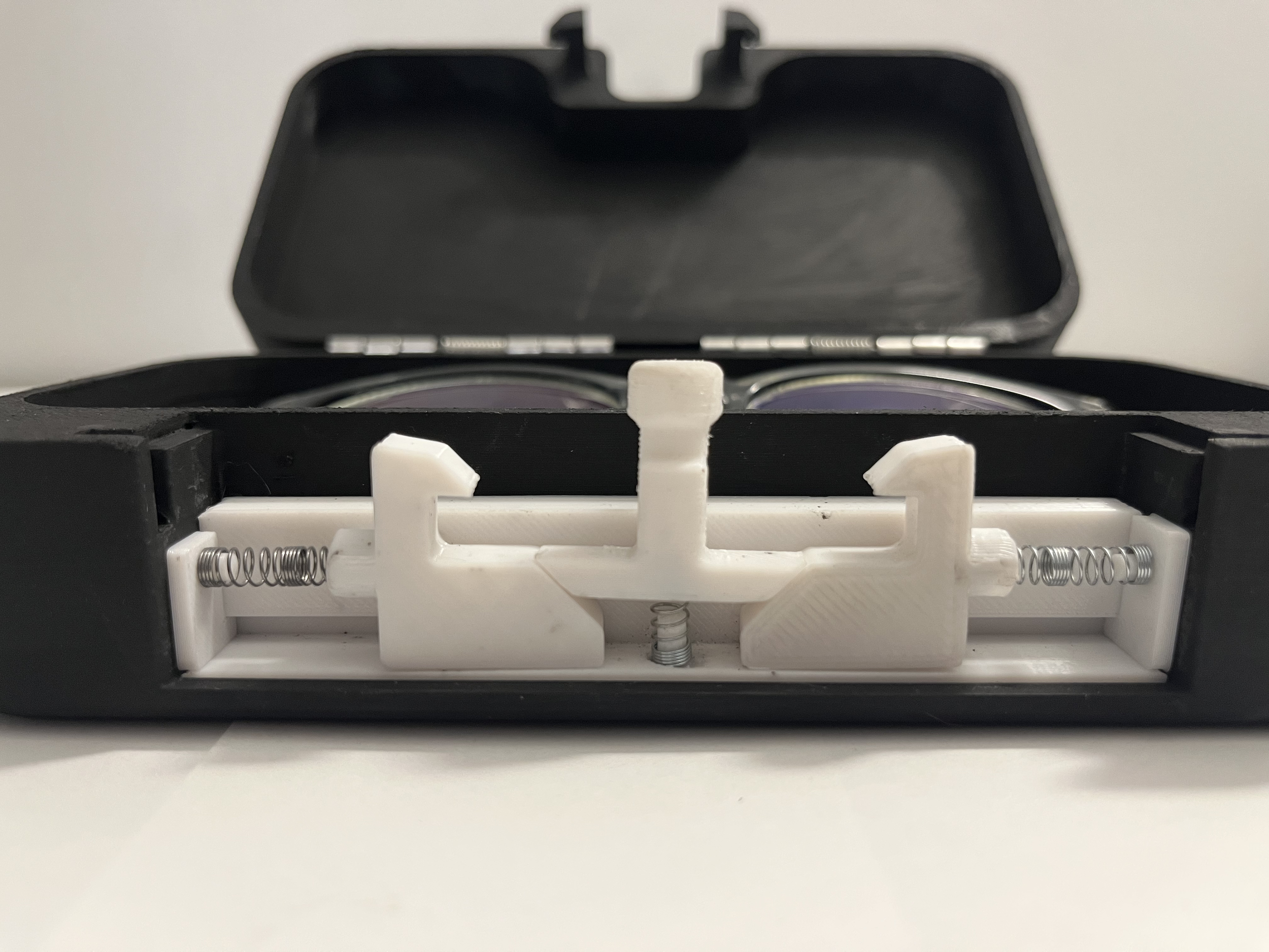
Button Mechanism Overview
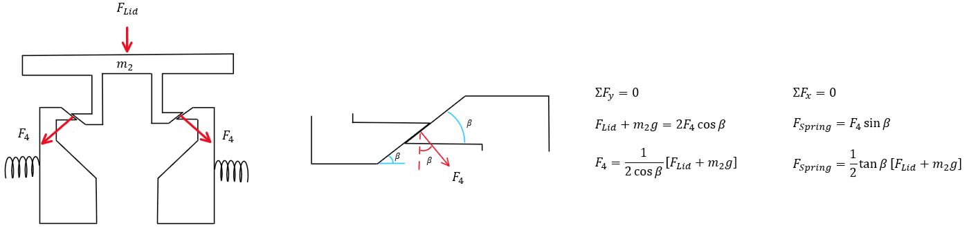
Lid Latch Force Calculation
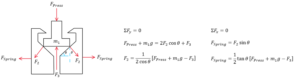
Button Actuation Force Calculation
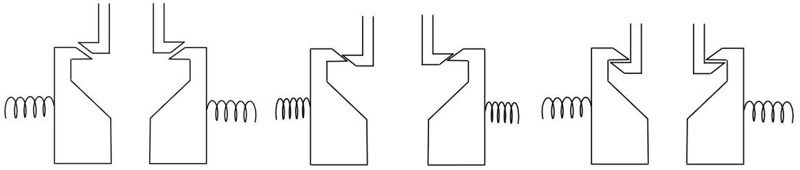
Displacement in X vs Y Calculation
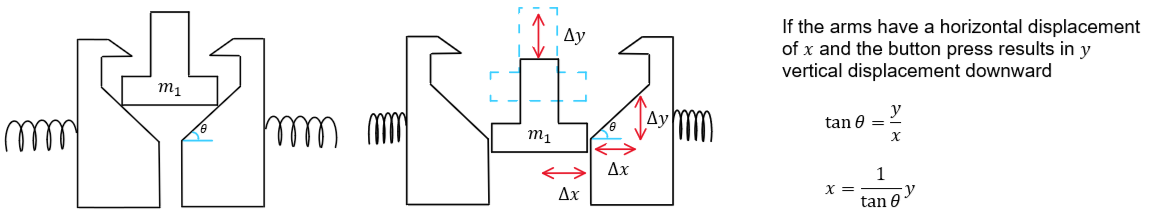
I selected a 45-degree angle for all interfaces because I was not significantly constrained by height or width. This also resulted in a 1:1 displacement in x-y, reducing complexity of the design. Additionally, 45 degree angles are straightforward to manufacture and commonly available in tooling. The spring constants were calculated in the appendix.
Final Design and Specifications
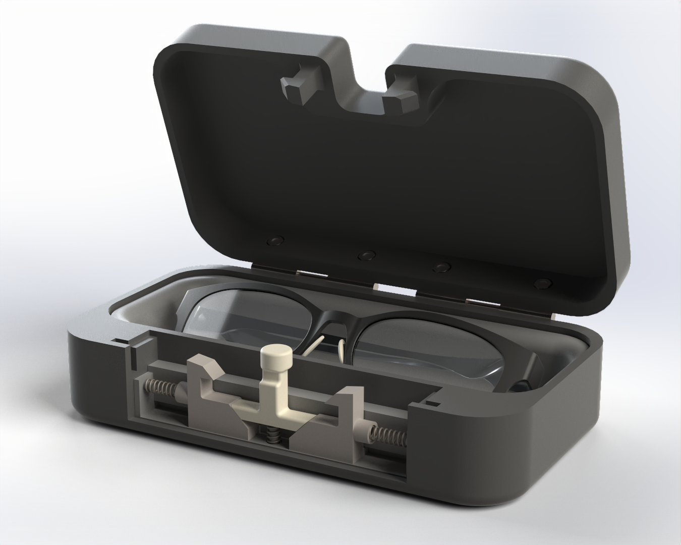
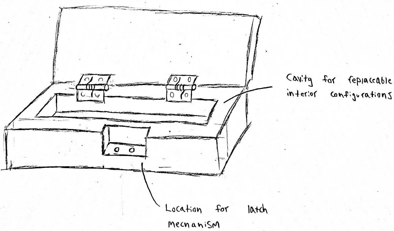
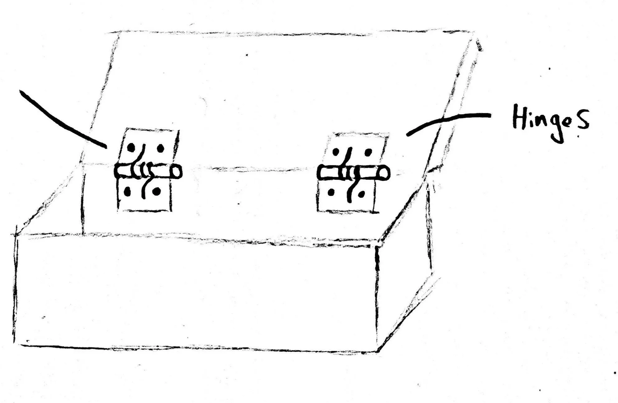
Design Components
Self-Opening Hinges to lift lid on button press
Lid with hooks to latch onto the button mechanism
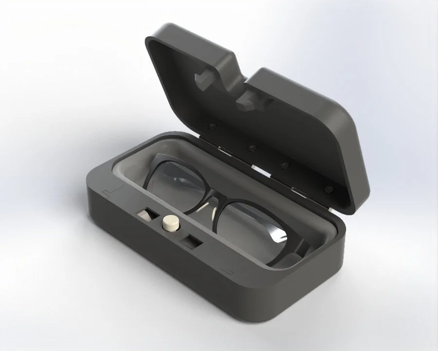
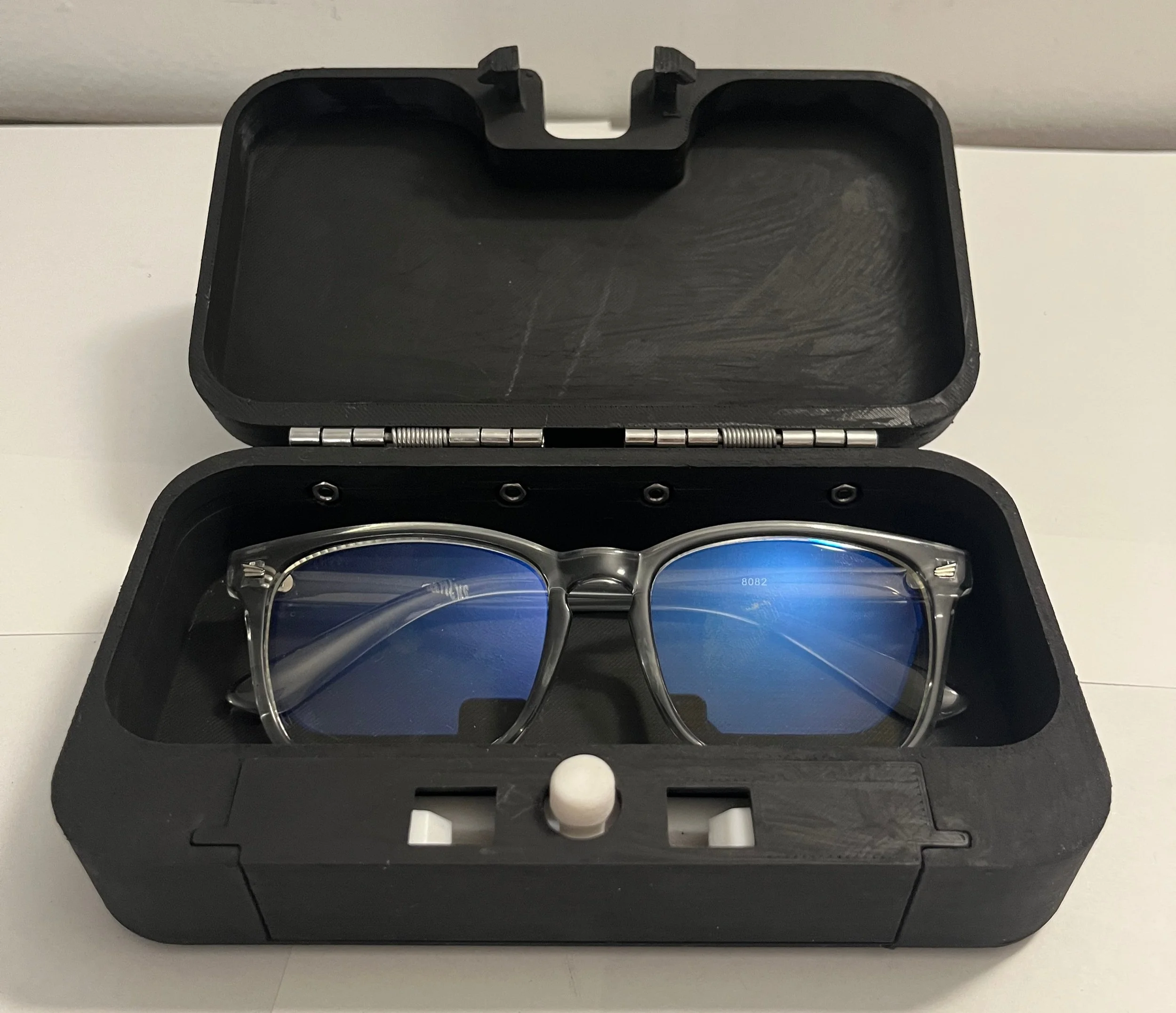
Interchangeable organizers, the photos show the glasses configuration
Design Specifications
Button Actuation Force of 0.3 kg
Button Travel Distance of 6 mm
Latching Force of 10 N
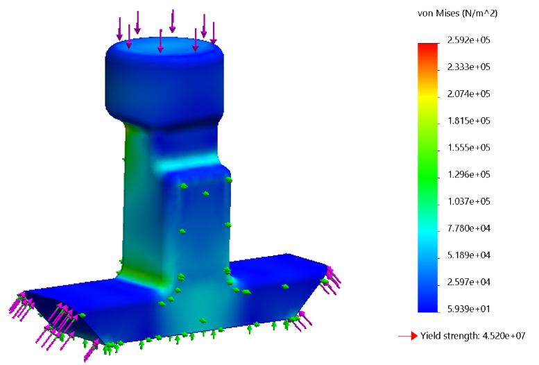
Finite Element Analysis (FEA)
Using PLA properties from MatWeb, I performed static FEA on the control arms and push button under maximum operational loads. Both components remained below the yield strength, ensuring no failure or plastic deformation.
Though FEA on 3D printed parts is not the most accurate due to varying material properties and anisotropy, it was a simple way for me to sanity check my work.

Product Assembly
3D Printed Parts

Hardware

Completed Product
Product Testing
Mechanism Analysis
To observe the system in action, I assembled a temporary transparent cover. Unlike the actual front plate, this cover lacks CAM guides, resulting in reduced stability. The system is significantly more stable during normal operation.
Opening Repetitions
To verify the repeatability, I conducted tests opening and closing the system rapidly. Its ability to perform consistently under these conditions confirmed its stability.
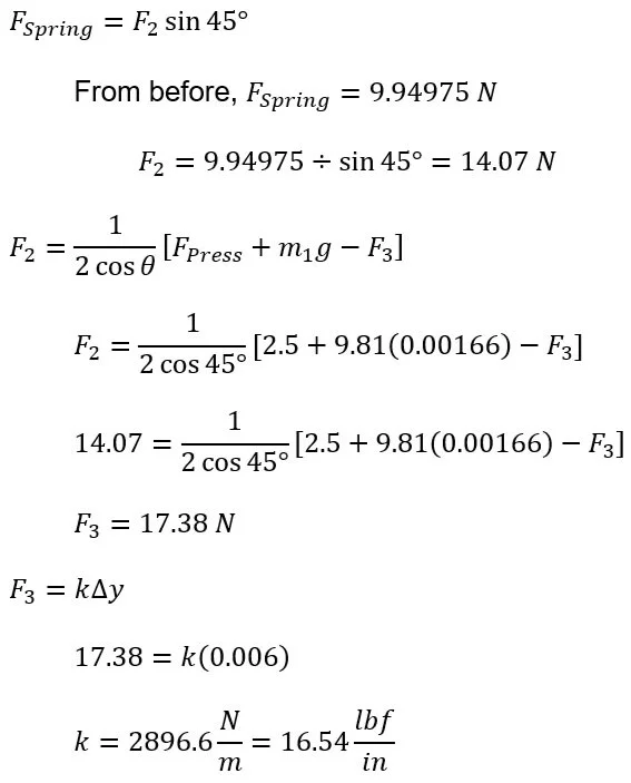
Appendix: Spring Constants Calculation
Since the equations depended on the mass of the components, I began by creating initial designs. I selected PLA over ABS as the 3D printing material due to its superior dimensional accuracy and reduced warping. After assigning PLA in SOLIDWORKS, the masses of the moving components were determined as follows: the lid weighed 89.95 grams, the button 1.66 grams, and the moving arms 2.49 grams. These values were then used in the calculations below to determine the required spring constants.
Horizontal Spring Calculation
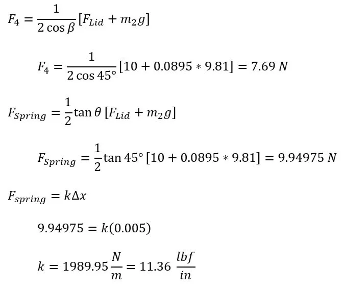
Vertical Spring Calculation